
Metal shell and electronic equipment

A metal shell, electronic equipment technology, applied in the direction of circuits, electrical components, conductive connections, etc., can solve problems such as increased cost, unstable contact, poor contact, etc., to achieve the effect of increasing costs

Inactive Publication Date: 2018-06-15
HUAQIN TECH CO LTD
View PDF10 Cites 3 Cited by
  • Summary
  • Abstract
  • Description
  • Claims
  • Application Information

AI Technical Summary

Problems solved by technology

[0003] The inventor found that there are at least the following problems in the prior art: in the prior art, the grounding is realized by contacting the upper surface of the screw column with the exposed copper part of the circuit board, and the contact is unstable; when the circuit board is deformed, poor contact is likely to occur
In addition, if the grounding is realized by adding shrapnel or conductive foam between the screw post and the circuit board, it will increase the cost

Method used


Image

  • Metal shell and electronic equipment
  • Metal shell and electronic equipment
  • Metal shell and electronic equipment

Examples


Embodiment Construction

[0019] In order to make the purpose, technical solutions and advantages of the embodiments of the present invention more clear, various implementation modes of the present invention will be described in detail below in conjunction with the accompanying drawings. However, those of ordinary skill in the art can understand that, in each implementation manner of the present invention, many technical details are provided for readers to better understand the present application. However, even without these technical details and various changes and modifications based on the following implementation modes, the technical solution claimed in this application can also be realized.

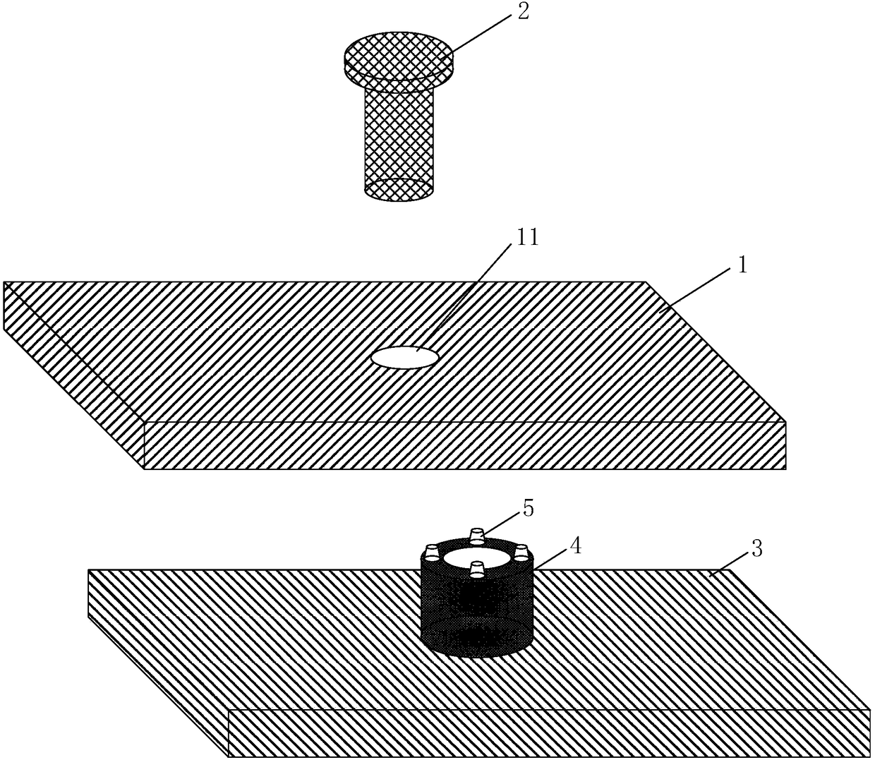
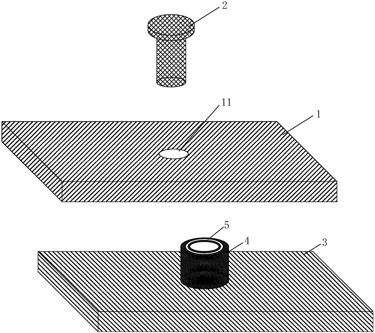
[0020] The first embodiment of the present invention relates to a metal casing, which is applied to electronic equipment, such as mobile phone and tablet computer, and the circuit board 1 of the electronic equipment is fixed to the metal casing by screws 2 . Please refer to figure 1 , the metal shell includ...


PUM

PropertyMeasurementUnit
Heightaaaaaaaaaa

Abstract

Embodiments of the invention relate to the technical field of electronic equipment, and disclose a metal shell and electronic equipment. The metal shell comprises a shell body and at least one screw column formed on the shell body; a convex part is formed on the upper surface of the screw column; a screw goes through a hole in a circuit board to be locked in the screw column; and the convex part props against a grounding part of the circuit board. The embodiments of the invention also provide the electronic device. Grounding stability of the circuit board can be maintained when the circuit board is deformed, and the cost is not increased basically.

Description

technical field [0001] Embodiments of the present invention relate to the technical field of electronic equipment, and in particular, to a metal casing and electronic equipment. Background technique [0002] In existing electronic equipment, the circuit board is grounded by fixing it to the metal casing, specifically: a screw post is formed on the metal case, and the screw passes through the opening on the circuit board and is locked on the screw post. At this time, the circuit board The ground exposed copper part of the board is in contact with the upper surface of the screw post, thereby realizing grounding. [0003] The inventor found that there are at least the following problems in the prior art: in the prior art, the grounding is realized by contacting the upper surface of the screw column with the exposed copper part of the circuit board, and the contact is unstable; when the circuit board is deformed, poor contact is likely to occur . In addition, if the grounding ...

Claims


Application Information

Patent Timeline
IPC IPC(8): H01R4/64H01R4/26H01R4/30
CPCH01R4/26H01R4/304H01R4/64
Inventor 邓勇进
Owner HUAQIN TECH CO LTD
Learn More