Condensate water waste heat recovery system

A waste heat recovery system and condensate water technology, applied in indirect heat exchangers, heat exchange equipment, heat exchanger types, etc., can solve the problems of underutilization of condensate water heat, damage to temperature structure, pollution, etc. Availability, improve energy efficiency, the effect of simple overall structure

Active Publication Date: 2018-06-15
GUANGDONG YEA ENERGY SAVING TECH
View PDF10 Cites 0 Cited by
  • Summary
  • Abstract
  • Description
  • Claims
  • Application Information

AI Technical Summary

Problems solved by technology

[0003] Direct discharge of condensed water leads to a waste of energy, resulting in the waste of heat energy provided by the initial combustion resources; at the same time, a large amount of condensed water with high calorific value has caused great damage and pollution to the environment
First of all, a large amount of heat in the condensed water is not fully utilized, and it is discharged into the environment, causing damage to the temperature structure of the water body and soil, and affecting the survival of animals, plants, and microorganisms in the water body and soil; secondly, the condensed water is rich in iron, calcium, Magnesium and other metal elements and other substances are often not subjected to special anti-pollution treatment during the discharge process. After the condensed water is directly discharged to the external water body and soil, it is easy to cause eutrophication of the water body and soil or change the pH of the water body and soil. Destroy the biosphere structure in the original water body and soil, which is extremely unfavorable to the environment
[0004] Our country advocates adhering to the sustainable development strategy in the process of scientific and technological development. It is necessary to strictly control environmental issues while technological innovation and economic progress. The current discharge of condensed water not only wastes the existing energy of the society, but also further damages the ecology. surroundings

Method used


Image

  • Condensate water waste heat recovery system

Examples


Embodiment

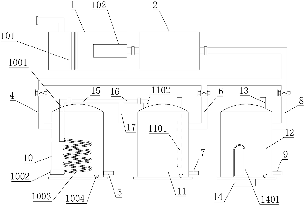
[0039] Such as figure 1 As shown, this embodiment discloses a condensate waste heat recovery system, including an antifouling treatment system and a heat recovery system. The water inlet of the antifouling treatment system is connected to the condensate pipe, and the water outlet of the antifouling treatment system is connected to the heat recovery system.

[0040] Specifically, the heat recovery system includes a hot air flow device and a double steam flow device separately communicated with the antifouling treatment system.

[0041] Hot air flow devices include dry heat devices and humid heat devices.

[0042] The dry heat device includes a first water collecting tank 10, on which a first water inlet 4 and a first water outlet 5 are arranged, the first water inlet 4 is connected to the water outlet of the antifouling treatment system, and the first water outlet 5 connected to the water return tank; the first water collecting tank 10 is also provided with a first air inlet 1...


PUM


Abstract

The invention discloses a condensate water waste heat recovery system. The system comprises an antifouling treatment system and a heat recovery system, the water inlet end of the antifouling treatmentsystem is connected to a condensate water pipe, and the water outlet end of the antifouling treatment system communicates with the heat recovery system; and the heat recovery system comprises a hot air flow device and a steam flow recurrence device which independently communicate with the antifouling treatment system. According to the condensate water waste heat recovery system, through the hot air flow device, external cold air can be heated into hot air to be supplied to people for use; through the steam flow recurrence device, steam can be regenerated after the condensed water is properlyheated to be supplied for external steam equipment requiring the steam for use; the system can provide dry hot air and wet hot air, active adjustment can be carried out according to requirements to provide the hot air with the corresponding temperature and humidity, the structure is simple, the function is complete, the system is greatly improved in the field of recycling of condensed water wasteheat, and therefore, the system is worthy of popularization and use.

Description

technical field [0001] The invention relates to the technical field of heat energy recovery and utilization, in particular to a condensed water waste heat recovery system. Background technique [0002] Since the industrial revolution, steam has been widely used in social life; in industrial production, steam, as an extremely versatile energy source, has an inseparable connection with almost all enterprises. A large amount of industrial water and coal-based energy are used to generate steam, and the heat of the steam is used to realize the industrial production process, and the condensed water produced after the steam releases part of the heat energy is often drained, and the condensed water has a large amount The heat generally accounts for about 20% to 30% of the total steam heat, and some equipment can be as high as 30%. [0003] The direct discharge of condensed water leads to a waste of energy, resulting in the waste of heat energy provided by the initial combustion res...

Claims


Application Information

Patent Timeline
IPC IPC(8): F28D7/08F28C3/06F28F21/08F22B1/28B03C1/30
Inventor 张帆谭正曲泓俐莫子耘黄雪云
Owner GUANGDONG YEA ENERGY SAVING TECH
Why Eureka
Try Eureka