Eureka AIR delivers breakthrough ideas for toughest innovation challenges, trusted by R&D personnel around the world.

Plastic profile embossing device

A plastic profile and embossing technology, which is applied in the field of plastic profile embossing devices, can solve the problems of non-adjustable position of embossing devices, loss of production enterprises, inability to disassemble, etc., to achieve reduced equipment investment, good economic value, and easy replacement Effect

Inactive Publication Date: 2018-06-15
伯奈聚合材料盐城有限公司
View PDF0 Cites 1 Cited by
  • Summary
  • Abstract
  • Description
  • Claims
  • Application Information

AI Technical Summary

Problems solved by technology

At present, embossing is realized through an embossing die. Once the embossing device and the die on the commonly used embossing die are fixed, they cannot be disassembled during the production process.
When the manufacturer needs embossed and non-embossed profiles in the profile production process, the parison needs to be cut off, and the embossing device is disassembled (installed) and then pulled again, which will generate a lot of waste and cause a lot of waste of profiles. It has brought great losses to the production enterprise; at the same time, the position of the existing embossing device cannot be adjusted, the embossing die head and the embossing device are fixed, and only one specification of profiled material can be embossed, and only One pattern, if you want to change the pattern, you need to reconfigure the embossing device and die head, the investment in equipment is too large, and the versatility is poor

Method used


Image

  • Plastic profile embossing device
  • Plastic profile embossing device

Examples


Embodiment Construction

[0019] The following will clearly and completely describe the technical solutions in the embodiments of the present invention with reference to the accompanying drawings in the embodiments of the present invention. Obviously, the described embodiments are only some, not all, embodiments of the present invention.

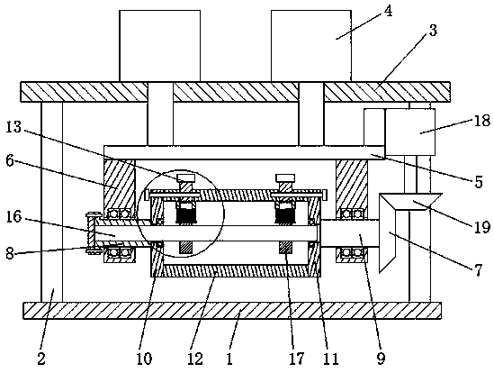
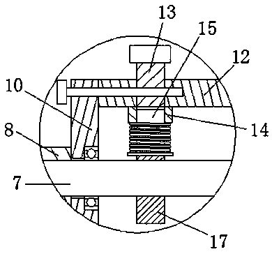
[0020] refer to Figure 1-2 , a plastic profile embossing device, including a workbench 1, the two sides of the top surface of the workbench 1 are connected with symmetrically distributed support columns 2, the top of the support columns 2 is connected with a top plate 3, and the top surface of the top plate 3 is installed with two A symmetrically distributed cylinder 4, the bottom output end of the cylinder 4 runs through the top plate 3 and is connected with a mounting plate 5, the two sides of the bottom surface of the mounting plate 5 are respectively connected with a bearing frame 6, and the bearing frame 6 is respectively rotatably connected with a shaft sleeve ...


PUM


Abstract

The invention discloses a plastic profile embossing device. The plastic profile embossing device comprises a workbench, wherein support columns which are symmetrically distributed are connected to both sides of the top surface of the workbench, a top plate is connected to the tops of the support columns, two air cylinders which are symmetrically distributed are installed on the top surface of thetop plate, the bottom output ends of the air cylinders penetrate through the top plate, a mounting plate is connected to the bottom output ends of the air cylinders, bearing frames are respectively connected to both sides of the bottom surface of the mounting plate, a shaft sleeve and a transmission shaft are rotatably connected to the bearing frames respectively, a first end cover is welded on the side surface of one side, which is close to the transmission shaft, of the shaft sleeve, a second end cover is welded on the side surface of one side, which is close to the shaft sleeve, of the transmission shaft, and a drum is connected to the end surfaces, which are close to each other, of the first end cover and the second end cover. The plastic profile embossing device has the advantages ofreasonable structure and good universality, quick switching of two operating modes of embossing and no embossing can be realized, the embossing requirements of different specifications of profiles canbe satisfied, an embossing die head is convenient to replace, and the cost of equipment is greatly reduced.

Description

technical field [0001] The invention relates to the technical field of profile processing equipment, in particular to a plastic profile embossing device. Background technique [0002] Plastic profile is a profile with plastic as the main material (such as iron sheet), which is widely used in construction and decoration industries. After embossing the surface of plastic profile, it is gradually accepted by more and more people because of its beautiful surface. favorite. At present, embossing is realized through an embossing die head, and once the embossing device and the die head on the commonly used embossing die head are fixed, they cannot be disassembled during the production process. When the manufacturer needs embossed and non-embossed profiles in the profile production process, the parison needs to be cut off, and the embossing device is disassembled (installed) and then pulled again, which will generate a lot of waste and cause a lot of waste of profiles. It has brou...

Claims


Application Information

Patent Timeline
IPC IPC(8): B29C59/02B29C53/16
CPCB29C59/02B29C53/16B29C59/002
Inventor 袁彩友
Owner 伯奈聚合材料盐城有限公司
Why Eureka
Eureka Blog
Learn More