Assembly welding tool of inner and outer fork part
A technology for welding tooling and parts, applied in the field of assembling tooling, can solve the problems of increased logistics time, low workpiece accuracy, large workshop space, etc., and achieves the effects of high fixing accuracy, improving welding accuracy, and reducing logistics time
- Summary
- Abstract
- Description
- Claims
- Application Information
AI Technical Summary
Problems solved by technology
Method used
Image

Examples
Embodiment 1
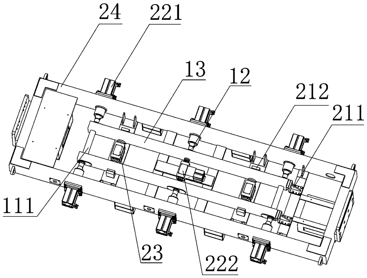
[0024] see figure 1 , figure 1 It is a schematic diagram of the butt welding tooling of the inner fork group. The workpiece mounting frame 24 is a rectangular frame structure. Three groups of symmetrical through holes are provided on both sides of the frame body. The positions of the through holes are determined by the positions of the long shaft sleeve 111 and the short shaft sleeve 12 of the fork rod 13 . First the fork rod 13 is placed on the workpiece mounting frame 24, the end positioning device 211 is fixed on the workpiece mounting frame 24 and is positioned at one end of the fork rod 13 to carry out lateral preliminary positioning to the position of the fork rod 13; the width positioning device 212 is fixed on the workpiece On the mounting frame 24 and outside the fork rod 13 , the width of the fork rod 13 is preliminarily positioned by the width positioning device 212 . The approximate position of the fork rod 13 is defined by the end positioning device 211 and the ...
Embodiment 2
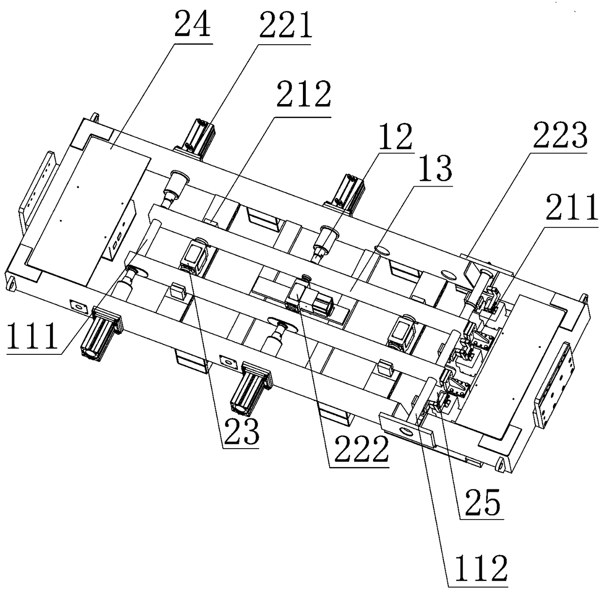
[0027] see figure 2 , figure 2 It is a schematic diagram of the welding tooling structure of the inner fork parts with two long shaft sleeves 111 of different lengths. The workpiece mounting frame 24 is a rectangular frame structure, and two groups of symmetrical through holes are opened on both sides of the frame body, and the positions of the through holes are determined by the positions of the long shaft sleeve 111 and the short shaft sleeve 12 . First the fork rod 13 is placed on the workpiece mounting frame 24, the end positioning device 211 is fixed on the workpiece mounting frame 24 and is located at one end of the fork rod 13, and the position of the fork rod 13 is initially positioned laterally by the end positioning device 211; The positioning device 212 is installed on the outside of the fork rod 13, and the width of the fork rod 13 is initially positioned by the width positioning device 212, and the approximate position of the fork rod 13 is limited by the preli...
Embodiment 3
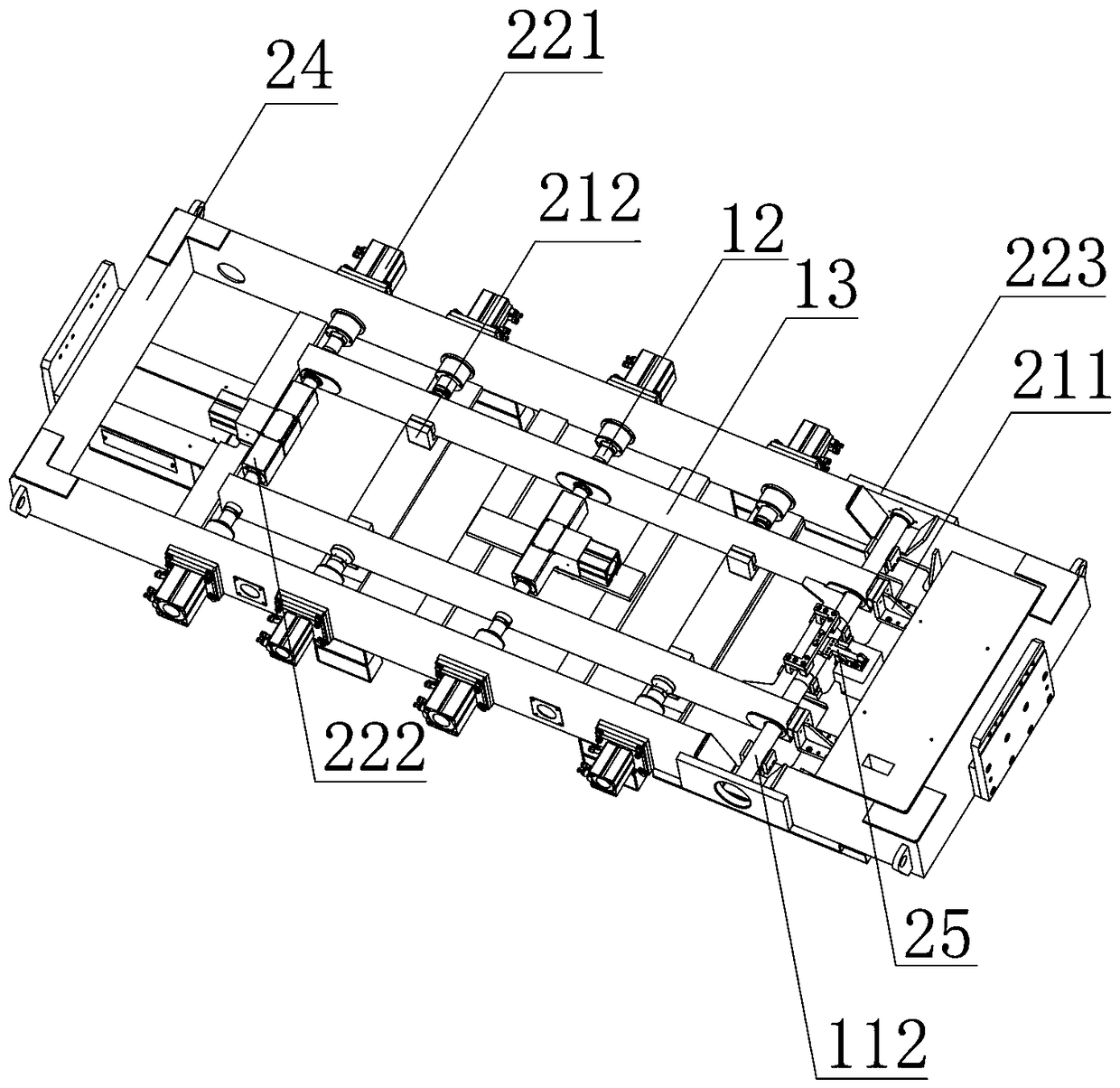
[0030] see image 3 , image 3 It is a schematic diagram of the welding tooling structure of the outer fork parts. The workpiece mounting frame 24 is a rectangular frame structure, and four groups of symmetrical through holes are opened on both sides of the frame body, and the positions of the through holes are determined by the positions of the short shaft sleeves 12 . First the fork rod 13 is placed on the workpiece mounting frame 24, the end positioning device 211 is installed on the workpiece mounting frame 24 and is positioned at one end of the fork rod 13, and the position of the fork rod 13 is initially positioned laterally by the end positioning device 211; The positioning device 212 is installed on the inner side of the fork rod 13, and the width of the fork rod 13 is positioned by the width positioning device 212, and the approximate position of the fork rod 13 is limited by the preliminary lateral positioning and the preliminary width positioning. The outer fork p...
PUM
 Abstract
Description
Claims
Application Information
 - Generate Ideas
- Intellectual Property
- Life Sciences
- Materials
- Tech Scout
- Unparalleled Data Quality
- Higher Quality Content
- 60% Fewer Hallucinations
Browse by: Latest US Patents, China's latest patents, Technical Efficacy Thesaurus, Application Domain, Technology Topic, Popular Technical Reports.
© 2025 PatSnap. All rights reserved.Legal|Privacy policy|Modern Slavery Act Transparency Statement|Sitemap|About US| Contact US: help@patsnap.com