
Cell combination method, cell splitting method, cell combination device, cell splitting device and base station

A cell and cell information technology, applied in the field of communication, can solve problems such as UE status and service cannot be guaranteed

Active Publication Date: 2018-06-12
ZTE CORP
View PDF12 Cites 3 Cited by
  • Summary
  • Abstract
  • Description
  • Claims
  • Application Information

AI Technical Summary

Problems solved by technology

[0005] Embodiments of the present invention provide a cell merging method, device, and base station, which are used to improve network performance, reduce co-channel interference, and solve the problem of releasing UEs during the merging and splitting process of multiple cells in the related art, resulting in UE status and Business cannot be guaranteed

Method used


Image

  • Cell combination method, cell splitting method, cell combination device, cell splitting device and base station
  • Cell combination method, cell splitting method, cell combination device, cell splitting device and base station
  • Cell combination method, cell splitting method, cell combination device, cell splitting device and base station

Examples


Embodiment 1

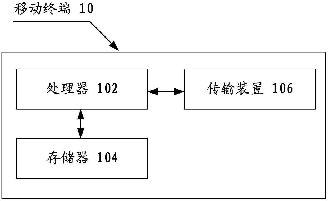
[0051] The method embodiment provided in Embodiment 1 of the present application may be executed in a mobile terminal, a computer terminal, or a similar computing device. Taking the mobile terminal running on the cell function as an example, figure 1 It is a block diagram of the hardware structure of a mobile terminal of a cell merging method according to an embodiment of the present invention. Such as figure 1 As shown, the mobile terminal 10 may include one or more (only one is shown in the figure) processor 102 (the processor 102 may include but not limited to a processing device such as a microprocessor MCU or a programmable logic device FPGA, etc.), for A memory 104 for storing data, and a transmission device 106 for communication functions. Those of ordinary skill in the art can understand that, figure 1 The shown structure is only for illustration, and it does not limit the structure of the above-mentioned electronic device. For example, the mobile terminal 10 may a...

application example 1

[0120] Figure 7 It is a flow chart of the multi-cell merging method according to the application example of the present invention, such as Figure 7 As shown, the process includes the following steps:

[0121] Scenario description: A high-priority UE enters a dense co-frequency cell on multiple floors.

[0122] S1, the high-priority UE accesses CELL A, and CELL A identifies the high-priority UE through the IMSI identification technology.

[0123] S2, CELL A sends reconfiguration signaling to the high-priority UE according to the pre-configured neighboring cells, which includes measurement objects, measurement events and measurement reports. In the application example of this patent, the CELLA sends the A4 event to the high-priority UE.

[0124] The meaning of the A4 event is that the neighboring cell is better than the absolute threshold, and its formula is as follows:

[0125] Mn+Ofn+Ocn-Hys>Thresh

[0126] Meanings and application examples of the parameters of the form...

application example 2

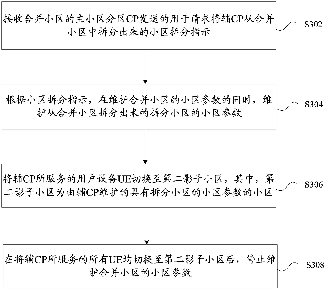
[0147] Figure 8 It is a flowchart of a method for dynamically splitting merged cells according to an embodiment of the present invention, such as Figure 8 As shown, the process includes the following steps:

[0148] Scenario description: A high-priority UE leaves the merged cell.

[0149] S1. When a high-priority UE is handed over from the merged cell to another cell, the merged cell will stop processing the access request of the new UE, and divide the target UE with CP B as the UE-level primary CP and single CP activation according to the uplink activation set . The primary CP A initiates a "cell split request" to the CP B, which carries relevant parameters of the target UE of the CP B.

[0150] S2. After the secondary CP B receives the "cell split request", the CP B sends the signal of the original cooperative cell CELL B while sending the signal of the merged cell.

[0151] S3, according to the LTE agreement, the CP B handovers the target UE to the coordinated cell.

...


PUM


Abstract

The invention provides a cell combination method, a cell splitting method, a cell combination device, a cell splitting device and a base station, wherein the cell combination method comprises the steps of: receiving a cell combination indication used for indicating combination of a first cell and a second cell and sent by the first cell; according to the cell combination indication, maintaining the cell parameter of the first cell while maintaining the cell parameter of the second cell; switching user equipment UE served by the second cell to a first shadow cell, and synchronizing informationof the switched UE to the first cell, wherein the first shadow cell is a cell maintained by the second cell and having the cell parameter of the first cell; and, stopping maintaining the cell parameter of the second cell after switching all UE served by the second cell to the first shadow cell and determining that the information of all the switched UE is synchronized to the first cell. By means of the cell combination method, the cell splitting method, the cell combination device, the cell splitting device and the base station provided by the invention, the fact that as many UE as possible has the best state and service effect can be effectively ensured.

Description

technical field [0001] The present invention relates to the field of communication, in particular, to a cell merging and splitting method, device and base station. Background technique [0002] In the 3GPP Long Term Evolution (LTE for short) system, in order to obtain better network performance, multi-cell coordination has become a widely concerned technology in the next generation wireless communication field. Among them, cell merging and splitting technology has become the best choice to avoid co-channel interference and frequent handover problems. This technology can realize the aggregation of multiple remote radio units (Radio Remote Unit, RRU for short) in a logical cell. In this networking scenario, the coverage area of ​​each RRU is called a cell partition (Cell Portion, CP for short). ). When the user terminal moves under different RRU coverage areas of the same logical cell, handover will not occur, and the problem of mobility is transformed into a problem of CP d...

Claims


Application Information

Patent Timeline
IPC IPC(8): H04W16/18H04W16/26H04W24/02
CPCH04W16/18H04W16/26H04W24/02H04W52/0206
Inventor 李中洋石昕娅杨厚一
Owner ZTE CORP
Learn More