
Test method and device for automatically adjusting Redriver

A technology of automatic adjustment and test method, applied in the direction of faulty hardware test method, error detection/correction, and detection of faulty computer hardware, etc., to improve test efficiency, save test time and manpower, and ensure accuracy

Inactive Publication Date: 2018-06-12
ZHENGZHOU YUNHAI INFORMATION TECH CO LTD
View PDF6 Cites 2 Cited by
  • Summary
  • Abstract
  • Description
  • Claims
  • Application Information

AI Technical Summary

Problems solved by technology

Therefore, there is a need for staff to debug the operation of the machine all the time

Method used


Image

  • Test method and device for automatically adjusting Redriver
  • Test method and device for automatically adjusting Redriver
  • Test method and device for automatically adjusting Redriver

Examples


Embodiment 1

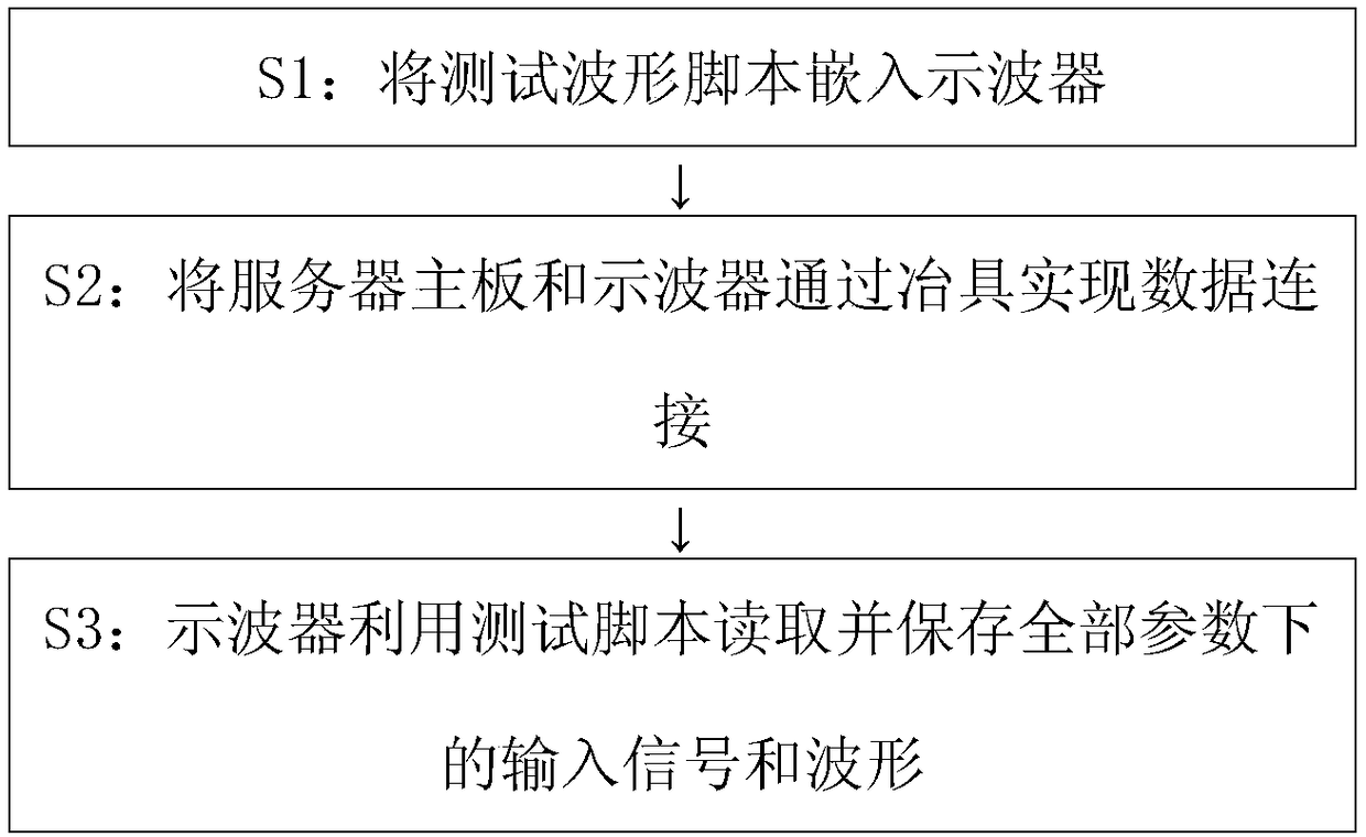
[0036] Such as figure 1 As shown, embodiment 1 of the present invention provides a kind of testing method that automatically adjusts Redriver, and described method comprises:

[0037] S1: Embed the test waveform script into the oscilloscope. The main function of the test waveform script is to automatically test the signal transmitted through the fixture and save the waveform in the oscilloscope by receiving the enable signal each time. During the test, the time of the test signal waveform is fixed.

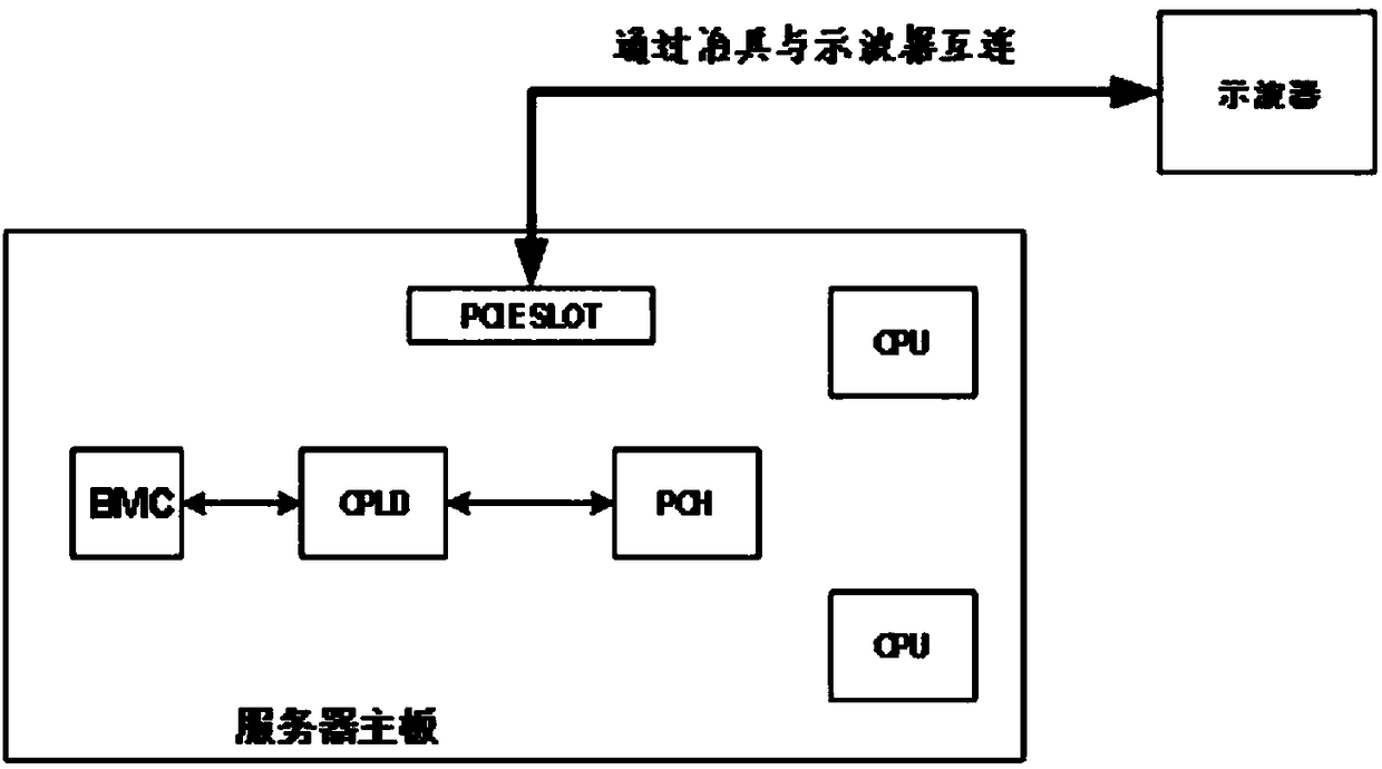
[0038] S2: Connect the server main board and the oscilloscope through the jig for data connection.

[0039] S3: The oscilloscope uses the test script to read and save the input signal and waveform under all parameters.

[0040] The specific implementation process of step S3 is:

[0041] S31: Burn the tested firmware into the BMC by using the burning device and burning software.

[0042] S32: Turn on the server, and the BMC writes the first set of values ​​into the Redriver re...

Embodiment 2

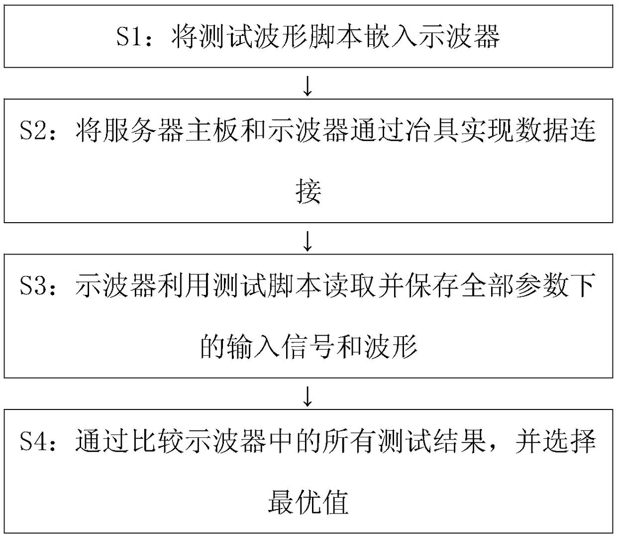
[0047] Such as figure 2 As shown, embodiment 2 of the present invention provides a kind of testing method that automatically adjusts Redriver, and described method comprises:

[0048] S1: Embed the test waveform script into the oscilloscope. The main function of the test waveform script is to automatically test the signal transmitted through the fixture and save the waveform in the oscilloscope by receiving the enable signal each time. During the test, the time of the test signal waveform is fixed.

[0049] S2: Connect the server main board and the oscilloscope through the jig for data connection.

[0050] S3: The oscilloscope uses the test script to read and save the input signal and waveform under all parameters.

[0051] The specific implementation process of step S3 is:

[0052] S31: Burn the tested firmware into the BMC by using the burning device and burning software.

[0053] S32: Turn on the server, and the BMC writes the first set of values ​​into the Redriver r...


PUM


Abstract

The invention provides a test method and device for automatically adjusting Redriver. The method comprises the steps that S1, a test waveform script is embedded into an oscilloscope; S2, a server mainboard and the oscilloscope are in data connection through a jig; S3, the oscilloscope reads and stores input signals and waveforms under all parameters through a test script. The device comprises theserver main board and a testing module, the server main board and the testing module are interconnected through the testing jig, the server main board is used for automatically inputting parameter adjusting signals, the testing module is used for reading signals transmitted by the testing jig and saving the corresponding waveforms. A machine is started to burn correct BMC firmware and the oscilloscope automation script so that people can leave a test table, and to-be-tested data can be read from the oscilloscope after testing so that time and labor for testing in the aspect can be saved for aproject, and then the cost is reduced.

Description

technical field [0001] The invention relates to the field of server testing, in particular to a testing method and device for automatically adjusting a Redriver. Background technique [0002] With the rapid development of the IT industry, the application of servers has become more and more common. And there are more and more server configuration requirements, some even to the harsh level. Due to these strict requirements, the traces on the PCB board are too dense or too long. The most common problem is that the high-speed signal line is too long, resulting in signal integrity problems. At this time, it is necessary to introduce the Redriver chip to make the high-speed signal passing through the Redriver chip use equalization, pre-emphasis and other technologies. Adjust and compensate for its loss and restore signal integrity at the receiving end. Currently Redriver is mainly for PCIE3.0 / 4.0, SAS / SATA, and USB3.0. [0003] At present, software adjustment is mainly used to...

Claims


Application Information

Patent Timeline
Patent Type & Authority Applications(China)
IPC IPC(8): G06F11/22
CPCG06F11/2205G06F11/2273
Inventor 李然
Owner ZHENGZHOU YUNHAI INFORMATION TECH CO LTD
Learn More