Device and method for diagnosing corrosion state of grounding electrode based on relative grounding resistance

A technology of ground resistance and corrosion state, which is applied in the field of diagnostic devices for ground electrode corrosion state, can solve problems such as engineering labor, influence of diffuser performance, single diagnosis result, etc., and achieve good guiding effect, elimination of influence, and high accuracy

Active Publication Date: 2018-06-12
CHONGQING UNIV
View PDF5 Cites 10 Cited by
  • Summary
  • Abstract
  • Description
  • Claims
  • Application Information

AI Technical Summary

Problems solved by technology

The value of grounding resistance fundamentally reflects the diffusion performance of the ground electrode and its surrounding soil, and its drainage performance is easily affected by the resistivity of the environmental soil. The change of the grounding resistance value cannot directly reflect the change of the corrosion state of the grounding electrode.
Moreover, the diagnostic result of using the grounding resistance value to diagnose the corrosion state of the grounding electrode is too simple, and it is impossible to distinguish the stages of different corrosion degrees of the grounding electrode.
Therefore, using the grounding resistance value to judge the corrosion state of the grounding electrode will easily lead to misjudgment and unnecessary engineering work.
[0004] To sum up, there are deficiencies in the method of diagnosing the corrosion state of the ground electrode through the measured value of the grounding resistance. The performance is that it is easily affected by the soil resistivity, which leads to inaccurate diagnosis results, and the classification of the corrosion state is too simple.

Method used


Image

  • Device and method for diagnosing corrosion state of grounding electrode based on relative grounding resistance
  • Device and method for diagnosing corrosion state of grounding electrode based on relative grounding resistance
  • Device and method for diagnosing corrosion state of grounding electrode based on relative grounding resistance

Examples


Embodiment Construction

[0054] The preferred embodiments of the present invention will be described in detail below with reference to the accompanying drawings.

[0055] 1. Design of a diagnostic device for ground electrode corrosion status based on relative ground resistance

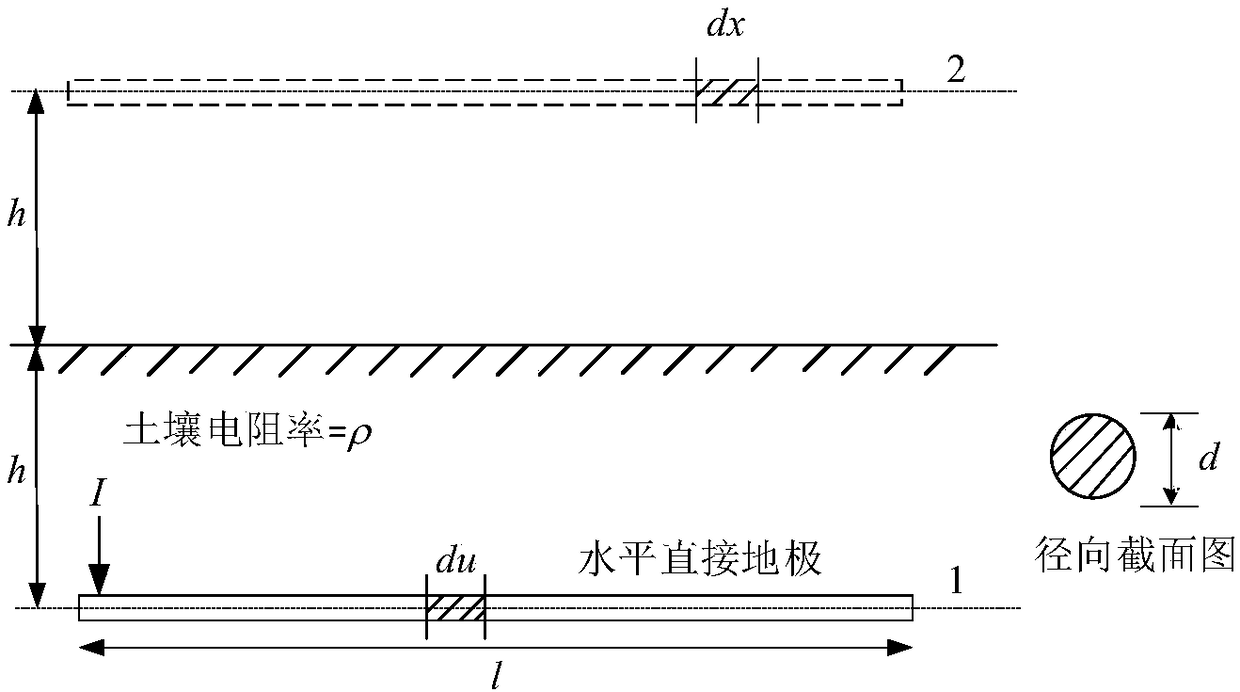
[0056] The ground electrode corrosion state diagnosis device based on the relative ground resistance is composed of two parts: the on-site measurement device and the central processing module. The measurement system is as follows: Figure 7 shown. The on-site measurement device includes: excitation source module, signal acquisition circuit module, central processing module, liquid crystal display module, power supply circuit, on-site measurement device mainly completes data signal acquisition, calculation and display of soil resistivity and polar resistance at the site tower Calculation and display of ground resistance, judgment and display of diagnosis results of ground electrode corrosion status.

[0057] The device uses t...


PUM


Abstract

The invention relates to a device and method for diagnosing the corrosion state of a grounding electrode based on relative grounding resistance, and belongs to the technical field of operation and management of power transmission and transformation equipment. The method comprises the following steps of S1, designing the grounding electrode and calculating the relative grounding resistance of the grounding electrode; S2, selecting a method for diagnosing the corrosion state of the grounding electrode according to different soil resistivities; S3, selecting a corrosion diagnosing criterion basedon the relative grounding resistance according to the soil resistivities; S4, designing and measuring the grounding resistance of the grounding electrode; S5, designing and measuring the soil resistivity of soil where the grounding electrode is located. The design method eliminates the influence of the soil resistivities on a diagnosis result of the corrosion state of the grounding electrode, achieves the classification of the corrosion state of the grounding electrode and further improves the accuracy of the diagnosis result of the corrosion state of the grounding electrode.

Description

technical field [0001] The invention belongs to the technical field of power transmission and transformation equipment operation and management, and relates to a device and method for diagnosing the corrosion state of a grounding electrode based on relative grounding resistance. Background technique [0002] As the necessary equipment to ensure the normal operation of the transmission line, the grounding electrode directly determines the power supply reliability of the transmission line. The operating environment of the tower ground electrode is harsh and susceptible to corrosion, which affects the dispersion performance of the ground electrode and increases the lightning tripping rate of the line. Therefore, the performance of the grounding electrode directly affects the reliability of the power supply of the transmission line, and plays a vital role in the operation of the power grid. [0003] At present, in the project, the measured value of the grounding resistance of t...

Claims


Application Information

Patent Timeline
Patent Type & Authority Applications(China)
IPC IPC(8): G01R27/20
CPCG01R27/20
Inventor 张占龙向睿梅道珺旦乙画王晶
Owner CHONGQING UNIV
Why Eureka
Try Eureka