
Transmitter diaphragm anti-high pressure shock and anti-freezing device

An anti-freezing device and anti-shock technology, applied in measuring devices, measuring fluid pressure, instruments, etc., can solve problems such as affecting the safe operation of the process, measuring and displaying dead points, and measuring diaphragm damage, achieving ingenious and compact structure design and ingenious design. , to ensure the effect of stable operation

Active Publication Date: 2020-12-08
SHANGHAI MEISHAN IRON & STEEL CO LTD
View PDF7 Cites 0 Cited by
  • Summary
  • Abstract
  • Description
  • Claims
  • Application Information

AI Technical Summary

Problems solved by technology

[0002] At present, instrument measurement transmitters are widely used in production process measurement systems. It is a signal conversion instrument that converts physical quantities such as pressure, flow, liquid level, etc. into electricity and sends them to the control system. From the perspective of application performance, pressure The transmitter is often due to sudden changes in working conditions, or the meter installed at the outlet of the water pump or oil pump. At the moment when the pump suddenly starts, the medium pressure suddenly rises beyond the measurement range of the transmitter, which can easily lead to damage to the measuring diaphragm. Dead pixels are displayed on the DCS screen, seriously affecting the safe operation of the entire process
In extremely cold weather, when the measuring pipeline of the pressure transmitter installed outdoors is at sub-zero temperature, the fault phenomenon of diaphragm freezing will also occur, which directly leads to the failure of the measurement display.

Method used

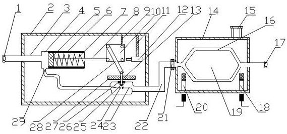
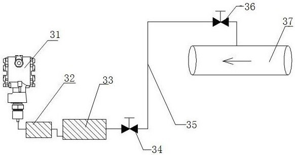
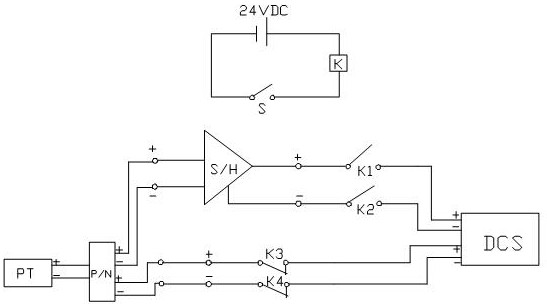

Image

  • Transmitter diaphragm anti-high pressure shock and anti-freezing device
  • Transmitter diaphragm anti-high pressure shock and anti-freezing device
  • Transmitter diaphragm anti-high pressure shock and anti-freezing device

Examples


Embodiment 1

[0020] Embodiment 1: see figure 1 , the transmitter diaphragm anti-high pressure shock and antifreeze device, the device includes an antifreeze assembly and an anti-shock assembly, the antifreeze assembly and the anti-shock assembly are connected through a communication pipe and a joint, and the anti-shock assembly includes an anti-shock assembly The device casing, the pressure induction tube arranged inside the casing, the pressure induction sleeve 4, the thrust conversion mechanism, the high and low pressure switching mechanism and the position detection mechanism, the pressure induction tube is arranged in the pressure induction sleeve, and the upper part of the thrust conversion mechanism is connected The position detection mechanism is connected to the high and low pressure switching mechanism below, and the thrust conversion mechanism includes a horizontal push rod 8, a square plate 10, a movable connecting rod 28 and a vertical push rod 13, and the movable connecting rod...


PUM


Abstract

The invention relates to a high-pressure-impact-prevention and antifreezing device of a transmitter diaphragm. The device comprises an antifreezing component and an impact prevention component. The antifreezing component and the impact prevention component are connected through a connection pipe and a joint. The impact prevention component comprises an impact prevention device shell, a guiding pressing pipeline, a guiding pressing casing pipe, a thrust conversion mechanism, a high and low pressure switching mechanism and a position detection mechanism, wherein the guiding pressing pipeline, the guiding pressing casing pipe, the thrust conversion mechanism, the high and low pressure switching mechanism and the position detection mechanism are arranged in the shell. The guiding pressing pipeline is arranged in the guiding pressing casing pipe. The upper portion of the thrust conversion mechanism is connected to the position detection mechanism, and a lower portion is connected to the high and low pressure switching mechanism. The structure of the device is simple and operation is convenient. The cut-off effect of a pipeline can be normally measured when there is high pressure and thesafety of the transmitter diaphragm is guaranteed.

Description

technical field [0001] The invention relates to a device, in particular to a high pressure impact and antifreeze device for a diaphragm of a transmitter, which belongs to the technical field of mechanical and electrical instrument control devices. Background technique [0002] At present, instrument measurement transmitters are widely used in production process measurement systems. It is a signal conversion instrument that converts physical quantities such as pressure, flow, liquid level, etc. into electricity and sends them to the control system. From the perspective of application performance, pressure The transmitter is often due to sudden changes in working conditions, or the meter installed at the outlet of the water pump or oil pump. At the moment when the pump suddenly starts, the medium pressure suddenly rises beyond the measurement range of the transmitter, which can easily lead to damage to the measuring diaphragm. The dead pixels are displayed on the DCS screen, w...

Claims


Application Information

Patent Timeline
Patent Type & Authority Patents(China)
IPC IPC(8): G01L19/06
CPCG01L19/0618
Inventor 成涛陆洪波卞祖亮
Owner SHANGHAI MEISHAN IRON & STEEL CO LTD
Learn More