Piston-cylinder assembly

A combination of equipment, piston and cylinder technology, applied to mechanical equipment, gas shock absorbers, springs, etc., can solve the problem that the middle position cannot be reproduced

Active Publication Date: 2018-06-12
STABILUS
View PDF9 Cites 2 Cited by
  • Summary
  • Abstract
  • Description
  • Claims
  • Application Information

AI Technical Summary

Problems solved by technology

Although the lockable piston-cylinder combination can also be positioned in an intermediate position between the moved-in end position and the moved-out end position, this intermediate position is not reproducible

Method used


Image

  • Piston-cylinder assembly
  • Piston-cylinder assembly
  • Piston-cylinder assembly

Examples


Embodiment Construction

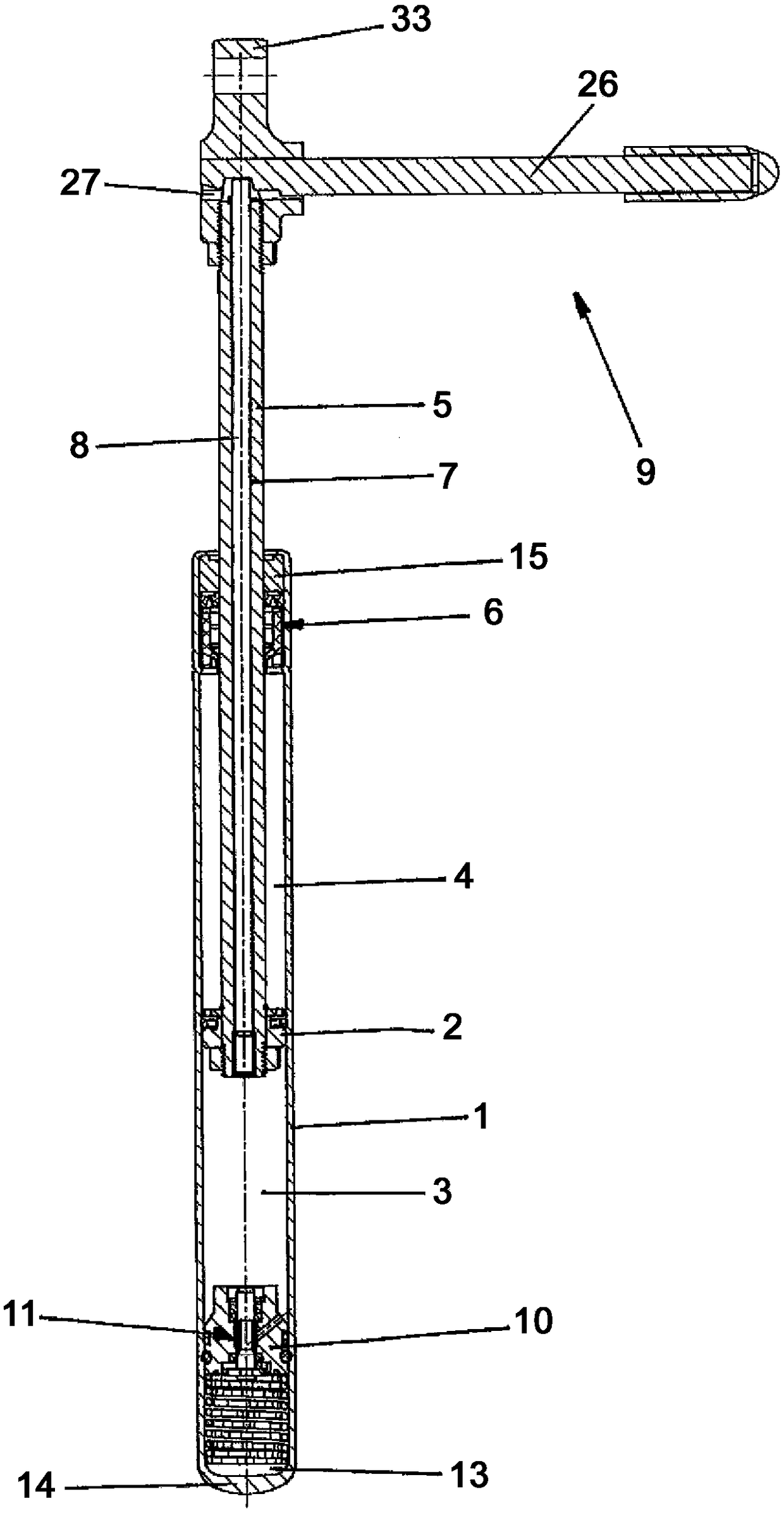
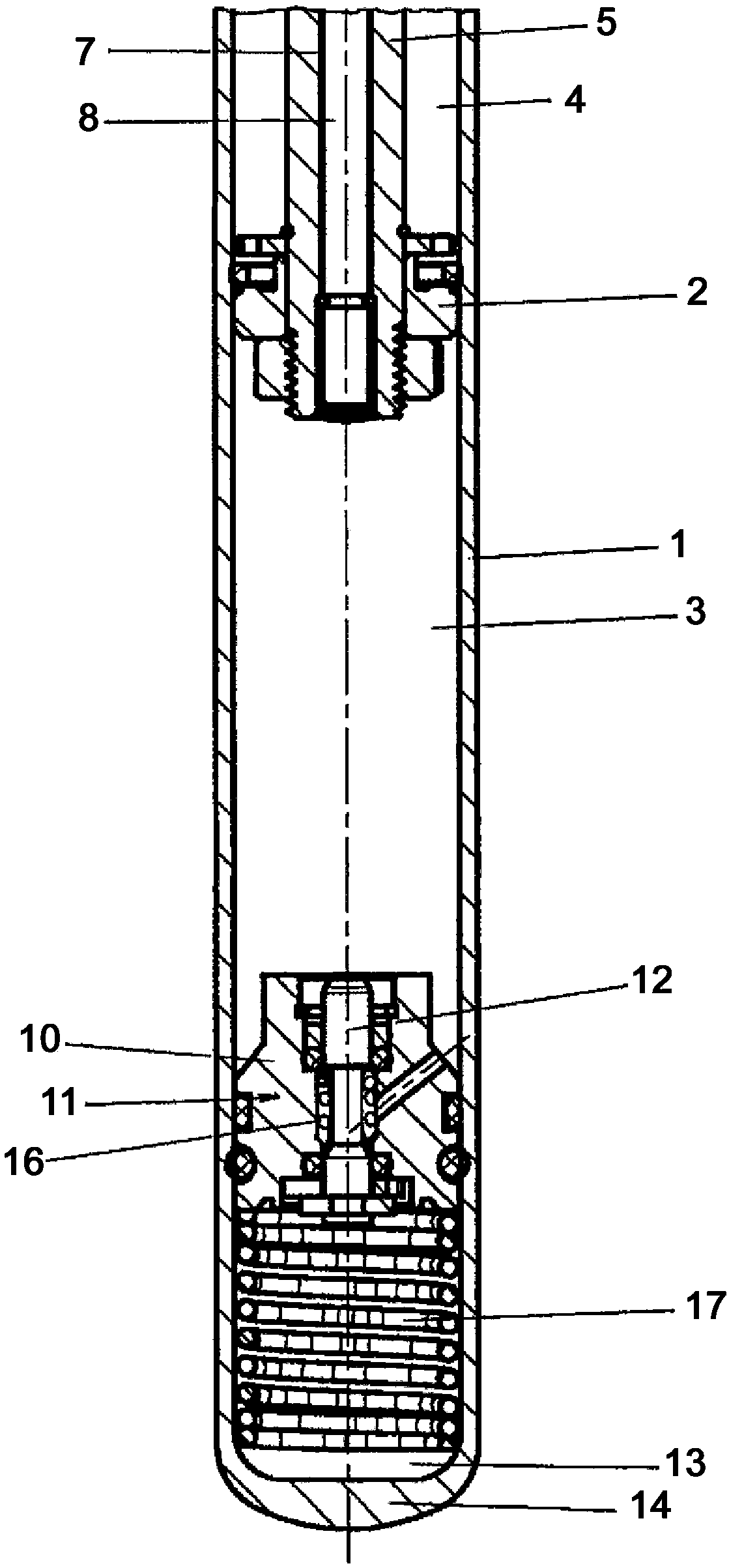
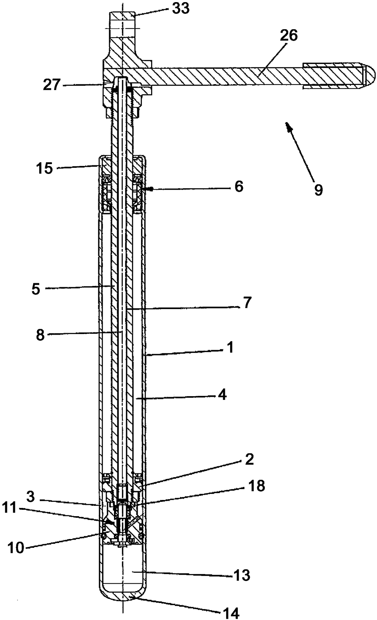
[0028] The piston-cylinder assembly shown in these figures has a cylinder 1, which is closed at its ends by a first closing part 14 and a second closing part 15, in which a piston 2 is arranged axially displaceable. . The piston 2 divides the liquid-filled interior of the cylinder 1 into a first working chamber 3 and a second working chamber 4 .

[0029] Arranged on one side of the piston 2 is a piston rod 5 , which extends coaxially through the second working chamber 4 and is guided outwards via the guide and seal 6 and the second closure 15 .

[0030] The piston rod 5 has a continuous axial passage 7 in which an actuating rod 8 is axially displaceably guided. Arranged at the outer end of the actuating rod 8 protruding from the piston rod 5 is an actuating device 9 by means of which the actuating rod 8 can be directly or indirectly driven axially displaceably.

[0031] In the region of the end of the first working chamber 3 opposite the piston rod 5 , a stop piston part 10 ...


PUM


Abstract

The invention relates to a piston-cylinder assembly which includes a cylinder 1 having a cylinder interior filled with a fluid and divided by a piston 2, which is axially displaceable in the cylinder1, into a first working space 3 and a second working space 4. A piston rod is arranged on piston and is guided through second working space 4 and through an end-side second closure 15 in a manner sealed off to the outside at the second end of the cylinder. The retraction stroke of piston 2 and piston rod 5 is restricted by a stop which is arranged in cylinder 1 and against which piston 2 comes tobear directly or indirectly, wherein the axial position of the stop in cylinder 1 is variably adjustable by an adjustment device.

Description

technical field [0001] The invention relates to a combined piston-cylinder device with a cylinder, which is filled with a liquid and whose cylinder interior is divided into a first working chamber and a second working chamber by a piston axially displaceable in the cylinder, the piston The cylinder assembly has a piston rod arranged on the piston, which passes through the second working chamber and is guided sealingly outward by a second end-side closure at the second end of the cylinder. Background technique [0002] In a piston-cylinder combination of this type, only the moved-in end position and the moved-out end position are reproducible positions, but not the intermediate positions. Although the lockable piston-cylinder assembly can also be positioned in an intermediate position between the moved-in end position and the extended end position, this intermediate position cannot be reproduced. Contents of the invention [0003] It is therefore the object of the present ...

Claims


Application Information

Patent Timeline
Patent Type & Authority Applications(China)
IPC IPC(8): F16F9/49F16F9/02
CPCF16F9/0218F16F9/0281F16F9/49F16F9/585F16F9/0227F16F9/0245F16F9/446F16F9/464F16F9/58
Inventor 拉尔斯·勒肯乌尔里希·普罗布斯特拉斐尔·皮尔罗特马库斯·米勒
Owner STABILUS
Why Eureka
Try Eureka