Modular sliding device and use method thereof

A sliding device, module technology, applied in the direction of linear motion bearings, bearings, shafts and bearings, etc., can solve the problems of low load capacity, large vibration and noise, achieve high load capacity, improve load capacity, straightening and trimming Simple effects with matching surfaces

Pending Publication Date: 2018-06-12
成都金士力科技有限公司
View PDF5 Cites 1 Cited by
  • Summary
  • Abstract
  • Description
  • Claims
  • Application Information

AI Technical Summary

Problems solved by technology

[0004] The purpose of the present invention is to provide a linear guide rail that uses ball rolling to move in the prior art, which requires cleaning and maintenance, has a low bearing capacity, and has relatively large vibration and noise during high-speed motion. A module sliding device and its use method. The module sliding device includes a guide rail, a slider and a slide piece matched with the slider. When in use, the slide piece is embedded and installed between the guide rail and the slide The slider forms an assembled overall structure, relying on the support of the slider, the slider slides smoothly on the guide rail in the form of sliding friction, avoiding frequent cleaning and maintenance of the guide rail, thereby improving production efficiency, and avoiding the The slider is in direct contact with the guide rail, which reduces wear and improves the service life of the equipment, and also has a high load-carrying capacity

Method used


Image

  • Modular sliding device and use method thereof
  • Modular sliding device and use method thereof
  • Modular sliding device and use method thereof

Examples


Embodiment 1

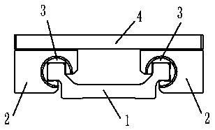
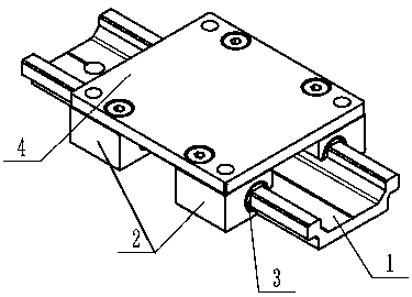
[0058] Such as Figure 1-7 As shown, the module sliding device includes a guide rail 1 with a rail 11, and a slider 2 installed on the rail 11, the contact surface of the slider 2 and the rail 11 is provided with a slide plate 3 for reducing friction, in:

[0059] The slider 2 is provided with a chute 21, and the slider 3 is installed in the chute 21. The slider 2 is also provided with a mounting structure for assembling the load bearing member 4, and the load bearing member 4 is used for to carry the load;

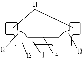
[0060] The guide rail 1 includes a base 12 for being installed on a support platform, and the rail 11 is extendedly connected to the base 12, so that the rail 11 is located outside the width range of the base 12, and the base 12 and The rails 11 extend in the same direction, and both have the same extension length.

[0061] The extension of the track 11 is connected to the base 12, which means that after the track 11 is connected to the base 12, the track 11 is outside...

Embodiment 2

[0073] Such as Figure 1-7 As shown, the method of using the module sliding device, when using the module sliding device as in Example 1, proceed according to the following steps:

[0074] a. Install the slider 3, install the slider 3 into the chute 21 of the slider 2, and keep the slider 3 and the slider 2 relatively fixed;

[0075] b. Install the slider 2, assemble the guide rail 1 and the slider 2, and make the track 11 of the guide rail 1 pass through the chute 21;

[0076] c. Fix the guide rail 1, and fix the guide rail 1 on the support platform through the installation hole 23 provided on the base 12 of the guide rail 1;

[0077] d. Install the load bearing member 4 and assemble the load bearing member 4 on the slider 2 .

[0078] The slider 3 is embedded and installed between the guide rail 1 and the slider 2, so that the slider 3 and the slider 2 form an assembled overall structure, and relying on the support of the slider 3, the slider 2 is smoothly on the guide rai...


PUM


Abstract

The invention relates to the technical field of automated matching equipment, in particular to a modular sliding device and a use method thereof. The modular sliding device comprises a guide rail provided with tracks and sliding blocks installed in the tracks. Sliding sheets used for reducing friction are arranged on the contact surfaces of the sliding blocks and the tracks. In use, the sliding sheets are embedded and installed between the guide rail and the sliding blocks, the sliding sheets and the sliding blocks form an assembled integrated structure, the sliding blocks are supported by thesliding sheets and slide on the guide rail stably in a mode of sliding friction, frequent cleaning and maintaining of the guide rail are avoided, and thus the production efficiency is improved; besides, direct contact of the sliding blocks and the guide rail is avoided through the sliding sheets, abrasion is reduced, and the service life of the equipment is prolonged; and meanwhile the modular sliding device has high carrying capacity.

Description

technical field [0001] The invention relates to the technical field of automation supporting equipment, in particular to a module sliding device and a using method thereof. Background technique [0002] The load-bearing structure of general modules adopts linear guide rails. Linear guide rails include roller linear guide rails, cylindrical linear guide rails and ball linear guide rails. Linear guide rails can be divided into sliding friction guide rails, rolling friction guide rails, elastic friction guide rails and fluid friction guide rails according to friction properties. type. In order to ensure the high-precision positioning of the load-bearing mechanism of the module, the steel ball rolling movement method is usually used, and the steel ball rolling has the advantage of a small friction coefficient, but this movement method has the disadvantages of difficult processing, complicated assembly and cleaning and maintenance. Disadvantages: Another linear guide way uses me...

Claims


Application Information

Patent Timeline
Patent Type & Authority Applications(China)
IPC IPC(8): F16C29/02
CPCF16C29/02
Inventor 王凤鸣吴顺辉邓浩宇
Owner 成都金士力科技有限公司
Why Eureka
Try Eureka