Eureka AIR delivers breakthrough ideas for toughest innovation challenges, trusted by R&D personnel around the world.

Rudder surface manufacturing method with aspect ratio being more than 9 times

A manufacturing method and aspect ratio technology, applied in the aviation field, can solve problems such as large deformation of the rudder surface, difficulty in controlling the weight of the rudder surface, and poor deflection angle accuracy

Inactive Publication Date: 2018-06-12
成都凯迪精工科技有限责任公司
View PDF6 Cites 5 Cited by
  • Summary
  • Abstract
  • Description
  • Claims
  • Application Information

AI Technical Summary

Problems solved by technology

With the current large aspect ratio (span: chord = 9:1), the rigidity of the movable rudder surface is poor, resulting in large deformation of the rudder surface during deflection, and poor deflection angle accuracy. During the flight, the rudder surface shakes violently, forming Resonance will seriously affect the service life. If a metal skeleton is added, it will be difficult to control the weight of the rudder surface

Method used


Image

  • Rudder surface manufacturing method with aspect ratio being more than 9 times
  • Rudder surface manufacturing method with aspect ratio being more than 9 times
  • Rudder surface manufacturing method with aspect ratio being more than 9 times

Examples


Embodiment 1

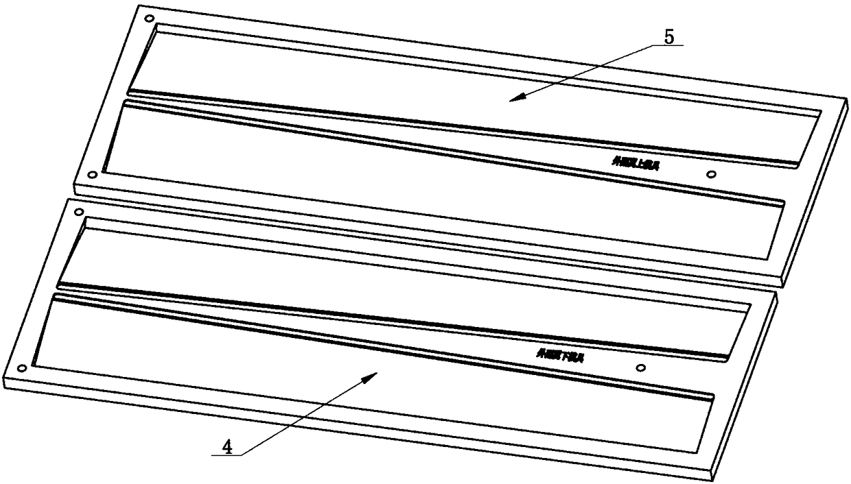
[0045]Example 1. Put the clamped mold into the oven, heat the room temperature to 105°C with the furnace, keep it warm for 15 minutes, continue to raise the temperature to 160° C, and keep it warm for 3 minutes; after coming out of the oven, dip the upper and lower molds with cotton cloth, and the mold temperature drops to 40 ℃~60℃; disassemble the mold, and demould the overall foaming component; clean the upper and lower molds of the aileron, and wrap the carbon fiber cloth with hand brush (or pre-impregnated) epoxy resin in the mold to complete the inner lining of step 10 Foaming parts and mold closing; the mold enters the oven again, heats up to 105°C with the furnace, and keeps warm for 1.6h; after it comes out of the oven, it is air-cooled to room temperature, and after the mold is disassembled, the rudder surface is demoulded, and all sides are trimmed to complete the manufacture of the rudder surface Work.

Embodiment 2

[0046] Example 2: Put the clamped mold into the oven, heat the room temperature to 92°C with the furnace, keep it warm for 11 minutes, continue to raise the temperature to 145° C, and keep it warm for 1.5 minutes; 40°C~60°C; disassemble the mold, and demould the overall foaming component; clean the upper and lower molds of the aileron, and wrap the inner lining of step 10 with hand-brushed (or pre-impregnated) epoxy resin carbon fiber cloth in the mold Foaming parts and mold closing; the mold enters the oven again, heats up to 92°C with the furnace, and keeps warm for 1.4 hours; after it comes out of the oven, it is air-cooled to room temperature, and after the mold is disassembled, the rudder surface is demoulded, and all sides are trimmed to complete the manufacture of the rudder surface Work.


PUM


Abstract

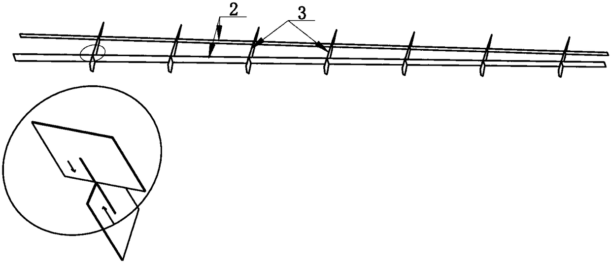
The invention belongs to the field of aviation, and particularly relates to a rudder surface manufacturing method with the aspect ratio being more than 9 times. According to the structural characteristics of the movable rudder surface of the large aspect ratio small fixed-wing aircraft and the manufacturing difficulties, from the aspect of improving the whole rigidity and intensity of outer ailerons, the whole foaming technology after a skeleton is embedded in a mold is skillfully adopted, a foaming internal lining piece is coated with a 0.2 mm glass fiber composite and mold forming is conducted to change local force bearing to whole force bearing of the ailerons, the rigidity and the intensity are greatly improved, mold outside skin molding is conducted, and the outline size of a rudder surface is well ensured. Through the technology, a process method for manufacturing the movable rudder surface of the small fixed-wing aircraft is found, and the aircraft movable rudder surface meetingthe large aspect ratio (the span direction to the chord direction being equal to 9:1) and high whole rigidity and intensity requirements can be manufactured through the method.

Description

technical field [0001] The invention belongs to the field of aviation technology, in particular to a method for manufacturing a rudder surface with an aspect ratio greater than 9 times. Background technique [0002] With the rapid development of small unmanned aircraft, the requirements for aircraft range and flight altitude are getting higher and higher. The inner and outer ailerons and rudders of small fixed-wing drones are required to be as light as possible to meet the strength requirements. However, the movable rudder surface of a small fixed-wing UAV, especially the inner and outer ailerons of the wing, has a large aspect ratio (span: chord = 9:1), and the production of a rudder surface that meets the overall rigidity requirements is the key technology. With the current large aspect ratio (span: chord = 9:1), the rigidity of the movable rudder surface is poor, resulting in large deformation of the rudder surface during deflection, and poor deflection angle accuracy. ...

Claims


Application Information

Patent Timeline
IPC IPC(8): B64F5/10
Inventor 殷贵刚石端张雷周军左小红田平
Owner 成都凯迪精工科技有限责任公司
Why Eureka
Eureka Blog
Learn More