Oscillators for mechanical watch movements

A watch movement and oscillator technology, applied to mechanically driven clocks, clocks, instruments, etc., can solve the problems of thinness and fragility

Active Publication Date: 2020-10-13
RICHEMONT INT
View PDF12 Cites 0 Cited by
  • Summary
  • Abstract
  • Description
  • Claims
  • Application Information

AI Technical Summary

Problems solved by technology

On the other hand, the number of parts and their arrangement make the implementation of this system very slim and fragile

Method used


Image

  • Oscillators for mechanical watch movements
  • Oscillators for mechanical watch movements
  • Oscillators for mechanical watch movements

Examples


Embodiment Construction

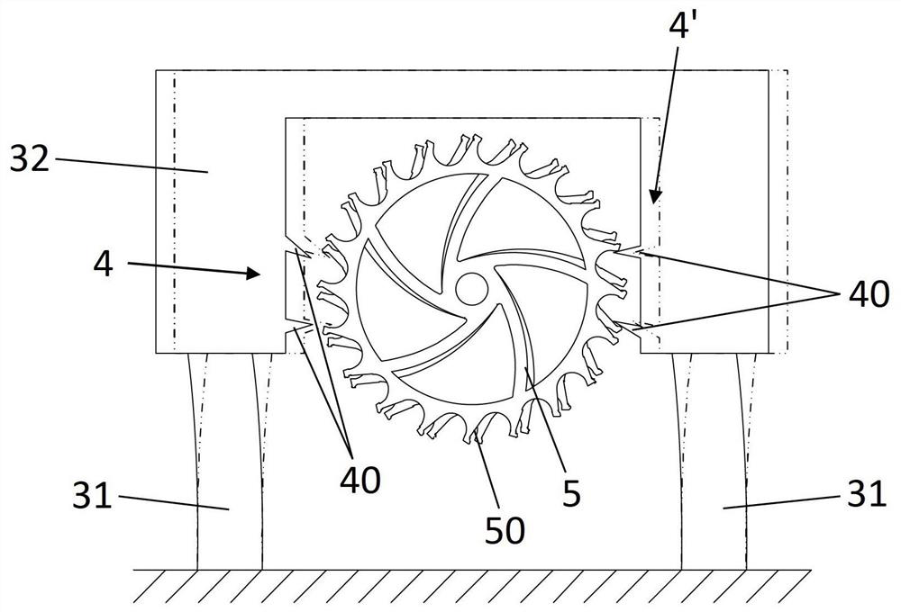
[0036] figure 1 A perspective view of an oscillator 1 according to one embodiment is shown. Oscillator 1 comprises escape wheel 5 and resonator 3 forming the time base of the oscillator. The resonator 3 includes a mass element 32 held in oscillation by at least two vibrating elements 31 . The mass element 32 comprises an anchoring portion 4 configured to cooperate directly with the escape wheel 5 to maintain the oscillation of the first resonator 3 and to allow the movement of the escape wheel 5 with each alternation of said oscillation .

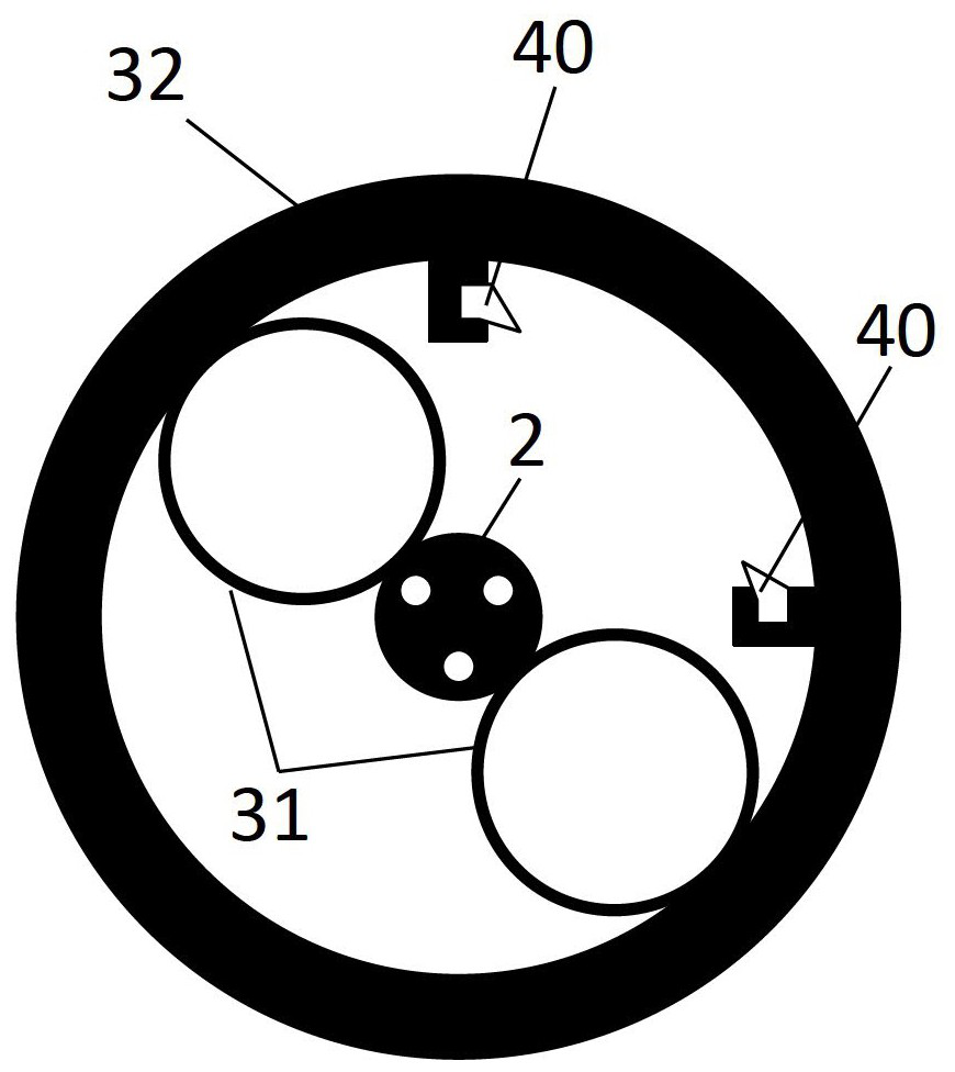
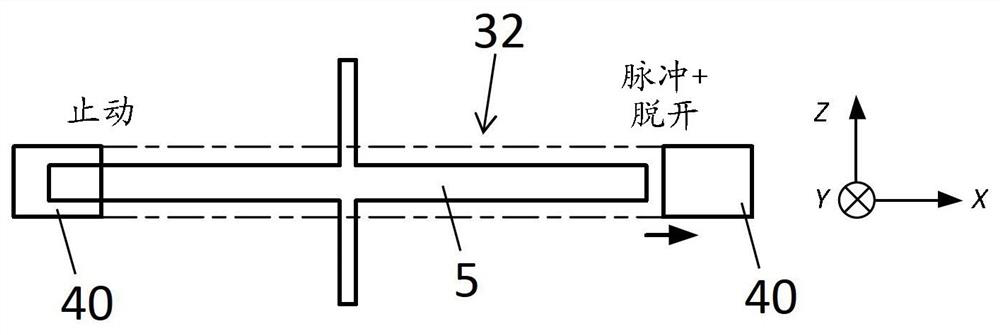
[0037] In particular, resonator 3 is formed by three vibrating elements 31 extending radially from center 12 in plane P. As shown in FIG. For the remainder of the description, we shall take, in a non-limiting manner, a transverse orientation "x" and a longitudinal orientation "y" and an axis "z" perpendicular to the longitudinal and transverse orientations, as indicated by the coordinate system shown in the drawings , the transverse or...


PUM


Abstract

The present invention relates to an oscillator for adjusting a mechanical timepiece movement, the oscillator (1) comprising an escapement wheel (5) and a resonator (3) that forms the time base of the oscillator (1); the resonator (3) including a mass element (32) that is kept in oscillation by at least two vibrating elements (31); the mass element (32) including at least one anchor portion (4) that is rigidly connected to the mass element (32), and is configured so as to directly engage with the escapement wheel (5) in order to maintain oscillations of the resonator (3), and so as to allow the escapement wheel (5) to move with each alternation of the oscillations; the first resonator (3) also including a base (2) that is intended to be mounted in a stationary or movable manner on the timepiece movement; the mass element (32) being supported only by the base (2) via the vibrating element (31).

Description

technical field [0001] The present invention relates to an oscillator for controlling a watch movement, which allows an oscillation frequency up to 5 kHz, and which has better stability and running precision when worn. The oscillator also allows for a higher quality factor Q while reducing tuning requirements. This oscillator is designed to replace a conventional oscillator, which notably includes a balance with sprung assembly and its anchor escapement pivoting on its own axis. The invention also relates to a timepiece movement comprising such an oscillator. Background technique [0002] In a timepiece movement, the function of the escapement is to transfer the energy it receives itself from the gear train driven by the mainspring to the resonator formed by the balance with sprung assembly. The escapement generally comprises an independent anchor oscillating about an axis pivoting in the plate. The mechanical connection between the anchor and the resonator, consisting of...

Claims


Application Information

Patent Timeline
Patent Type & Authority Patents(China)
IPC IPC(8): G04B17/04
CPCG04B15/06G04B15/14G04B17/045G04B43/007
Inventor O.卡伦E.克莱恩A.赫劳德J.祖彻尔
Owner RICHEMONT INT
Why Eureka
Try Eureka