
Temperature and strain measurement technique during cryoablation

A slender, bulky technology that is used in the field of equipment to identify ablation tissue areas, and can solve problems such as rapid fluorescence decay

Active Publication Date: 2018-06-08
美敦力快凯欣有限合伙企业
View PDF4 Cites 15 Cited by
  • Summary
  • Abstract
  • Description
  • Claims
  • Application Information

AI Technical Summary

Problems solved by technology

In this case, however, there may be artifacts in the temperature measurement if the sensor is located near the cryoballoon
For example, heat exchange between the cryoballoon and the sensor may produce a rapid decay of fluorescence

Method used


Image

  • Temperature and strain measurement technique during cryoablation
  • Temperature and strain measurement technique during cryoablation
  • Temperature and strain measurement technique during cryoablation

Examples


Embodiment Construction

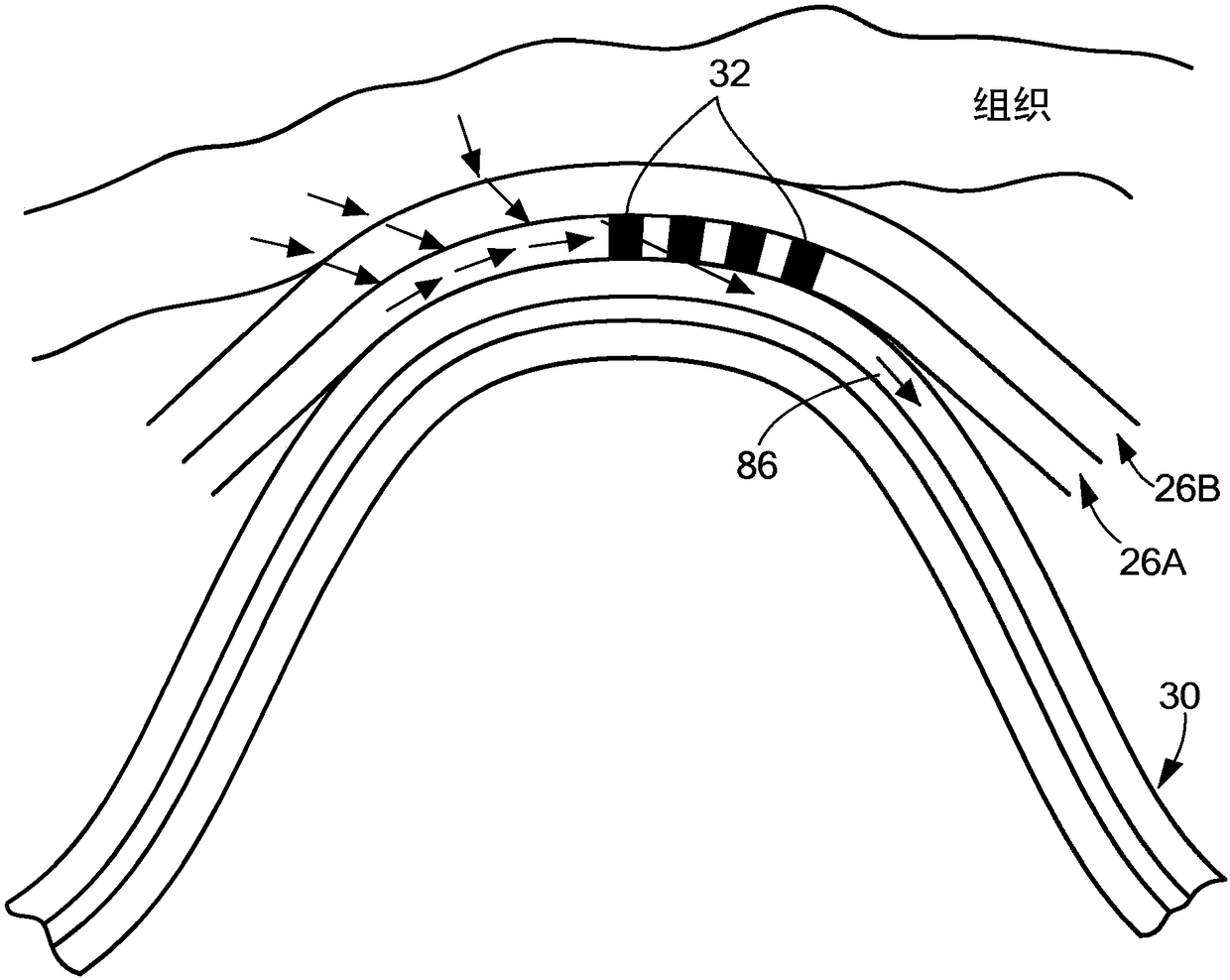
[0031] The present invention relates to a device, system and method for identifying regions of ablated tissue. The present invention also relates to a device, system and method for assessing contact between a therapeutic element and tissue and / or for assessing an obstruction of a body cavity by said therapeutic element. In particular, the devices, systems and methods may include one or more fiber optic sensors and a processing unit for receiving emitted light and / or reflected light from tissue and making decisions about ablation based on the received light. One or more determinations of tissue, tissue contact and / or obstruction.

[0032] now refer to figure 1 , shows an exemplary cryotherapy system including a device with a fiber optic sensor for monitoring tissue temperature. System 10 may generally include a therapeutic device, such as cryotherapy catheter 12 , for thermally treating a tissue region, and a console 14 that houses various system 10 controls. System 10 may b...


PUM


Abstract

Disclosed are a device, system, and method for identifying an area of ablated tissue and / or assessing contact between a treatment element and tissue and / or assessing occlusion of a body lumen by the treatment element. Specifically, the device, system, and method may include a device having one or more fiber sensors and a processing unit for receiving emitted and / or reflected light from tissue andmaking one or more determinations based on the received light regarding ablated tissue, tissue contact, and / or occlusion. Each of the fiber sensors may include at least one multi mode waveguide segment and at least one single mode waveguide segment, or each of the fiber sensors may be single mode waveguide including fiber Bragg grating for assessing strain of a treatment element by tissue contact.The processing unit may include a beam processing apparatus and a hyperspectral imaging and analysis apparatus, and may optionally include a light source.

Description

technical field [0001] The present invention relates to a device, system and method for identifying regions of ablated tissue. The present invention also relates to a device, system and method for assessing contact between a therapeutic element and tissue and / or for assessing an obstruction of a body cavity by said therapeutic element. In particular, the devices, systems and methods may include one or more fiber optic sensors and a processing unit for receiving emitted light and / or reflected light from tissue and making decisions about ablation based on the received light. One or more determinations of tissue, tissue contact and / or obstruction. Background technique [0002] Arrhythmia is a condition in which the normal rhythm of the heart is interrupted. Certain types of cardiac arrhythmias, including ventricular tachycardia and atrial fibrillation, can be treated with ablation (eg, radiofrequency (RF) ablation, cryoablation, ultrasound ablation, laser ablation, microwave ...

Claims


Application Information

Patent Timeline
IPC IPC(8): A61B18/02A61B5/00
CPCA61B5/4836A61B2562/0233A61B18/1492A61B2018/00375A61B2018/00821A61B2018/0212A61B2018/0262A61B5/0075A61B2017/00061A61B5/01A61B18/02A61B2018/0022A61B2018/00577A61B2018/00714A61B2018/00791A61B2562/0271A61B2562/0238
Inventor R·萨拉
Owner 美敦力快凯欣有限合伙企业
Learn More