
Wide-angle scanning phased array antenna with large element spacing and wide-angle scanning based on electromagnetic bandgap structure

An electromagnetic bandgap structure and phased array antenna technology, which is applied in the field of radar technology, can solve problems such as damaged working bandwidth and large unit size, and achieve the effects of easy processing and manufacturing, good broadband, and reduced manufacturing costs

Active Publication Date: 2020-09-25
UNIV OF ELECTRONICS SCI & TECH OF CHINA
View PDF7 Cites 0 Cited by
  • Summary
  • Abstract
  • Description
  • Claims
  • Application Information

AI Technical Summary

Problems solved by technology

However, the large unit size will cause scanning blind spots when scanning the E surface, which will damage the working bandwidth for large-angle scanning.

Method used


Image

  • Wide-angle scanning phased array antenna with large element spacing and wide-angle scanning based on electromagnetic bandgap structure
  • Wide-angle scanning phased array antenna with large element spacing and wide-angle scanning based on electromagnetic bandgap structure
  • Wide-angle scanning phased array antenna with large element spacing and wide-angle scanning based on electromagnetic bandgap structure

Examples


Embodiment 1

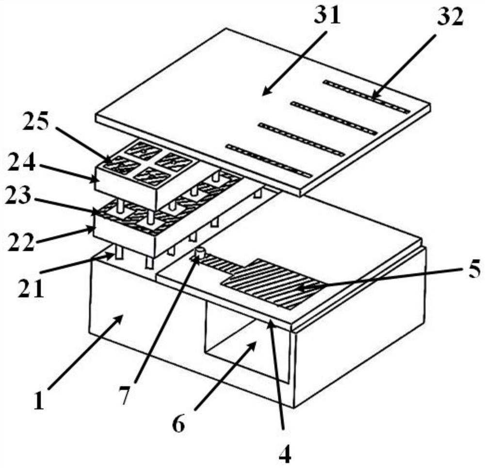
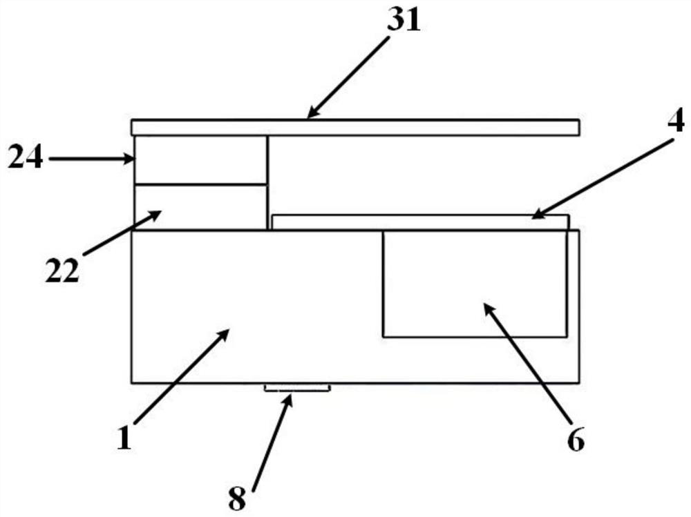
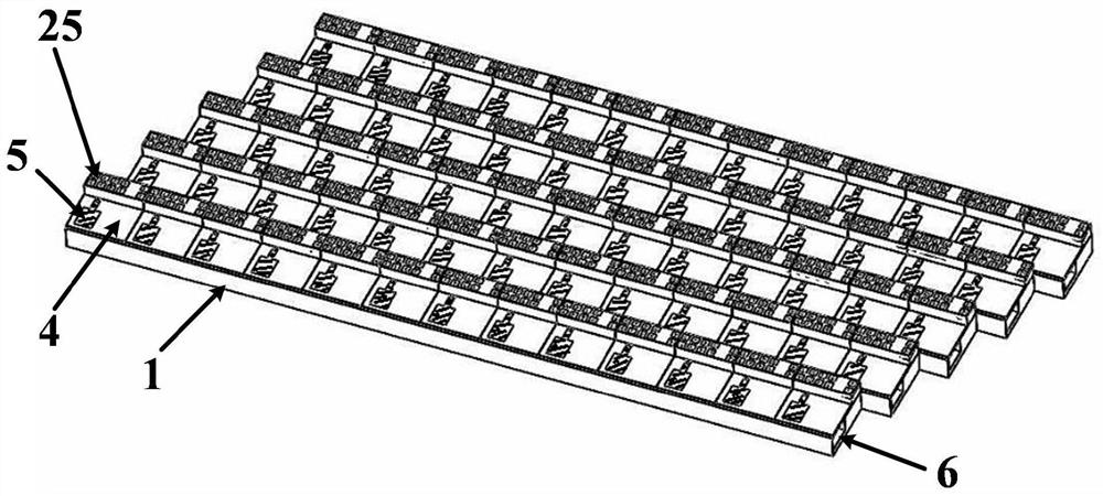
[0024] The large element spacing wide-angle scanning phased array antenna based on the electromagnetic bandgap structure of this embodiment adopts a 13×5 planar array form, and the designed array works at 7-13 GHz. Such as figure 2 The array units shown are arranged in a triangular grid, and the size of the array element is 14.6mm×13mm, which is larger than half the wavelength of the high-frequency end operating frequency. Below is a metal floor 1 with a rectangular connection groove 6, the groove is 3.5mm deep and 6mm wide, and there is no medium filling inside the groove. The middle dielectric plate 4 has a thickness of 0.5 mm and a dielectric constant of 2.2, and is bonded to the metal floor 1 , with a microstrip feeder 5 printed on its upper surface. One end of the coaxial core 7 is connected to the SMA connector, and the other end passes through the metal floor 1 and the middle dielectric board 4 to connect to the feeding point of the microstrip feeder 5, and the other e...


PUM


Abstract

The invention discloses a wide-angle scanning phased array antenna with large unit spacing based on an electromagnetic bandgap structure, which belongs to the technical fields of radar and wireless communication. The antenna unit is arranged in a triangular grid, including an upper dielectric board, a middle dielectric board, and a lower metal floor; the middle dielectric board with microstrip feeders printed on the upper surface is attached to the metal floor with connecting grooves on the upper surface; coaxial The inner core of the line is connected to the feeding point of the microstrip feeder, and the other end of the microstrip feeder is located above the connection groove for coupling and feeding; the upper surface of the upper dielectric board is printed with a metal strip line; between the upper dielectric board and the metal floor is also provided with Electromagnetic bandgap structures that suppress surface waves. The invention introduces the electromagnetic band gap structure, effectively eliminates the scanning blind spot by suppressing the propagation of the surface wave, and realizes the characteristics of wide angle and wide band. It has the advantages of large unit size and simple structure, which can greatly reduce the manufacturing cost of large phased array antennas in practical applications.

Description

technical field [0001] The invention belongs to the field of radar technology and wireless communication technology, and specifically relates to a phased array antenna with large unit spacing and wide-angle scanning based on an electromagnetic bandgap structure, in particular to wide-band and wide-angle scanning, and is suitable for microwave, millimeter wave and other radars and communications system. Background technique [0002] Phased array antennas have been widely used in military and commercial fields because of their fast beam scanning capabilities and no shortcomings such as time delay and motion inertia of traditional mechanical beam scanning systems. In the past few decades, with the demand for multifunctional systems on military airborne platforms, the research on broadband and wide-angle phased array antennas has also received extensive attention. In the design process of traditional rectangular grid phased array antennas, in order to prevent grating lobes from...

Claims


Application Information

Patent Timeline
Patent Type & Authority Patents(China)
IPC IPC(8): H01Q9/04H01Q1/50H01Q1/48
CPCH01Q1/48H01Q1/50H01Q9/0457
Inventor 屈世伟邹文慢王亚茹杨仕文胡俊
Owner UNIV OF ELECTRONICS SCI & TECH OF CHINA
Learn More