
Method for detecting solid-state laser radar device

A laser radar and detection method technology, applied in radio wave measurement systems, instruments, etc., can solve the problems of complex structure, numerous assembly processes, and large space occupation, and achieve the goal of expanding the detection area, improving the rational use of power, and occupying a small space Effect

Inactive Publication Date: 2018-06-08
BENEWAKE BEIJING TECH CO LTD
View PDF2 Cites 24 Cited by
  • Summary
  • Abstract
  • Description
  • Claims
  • Application Information

AI Technical Summary

Problems solved by technology

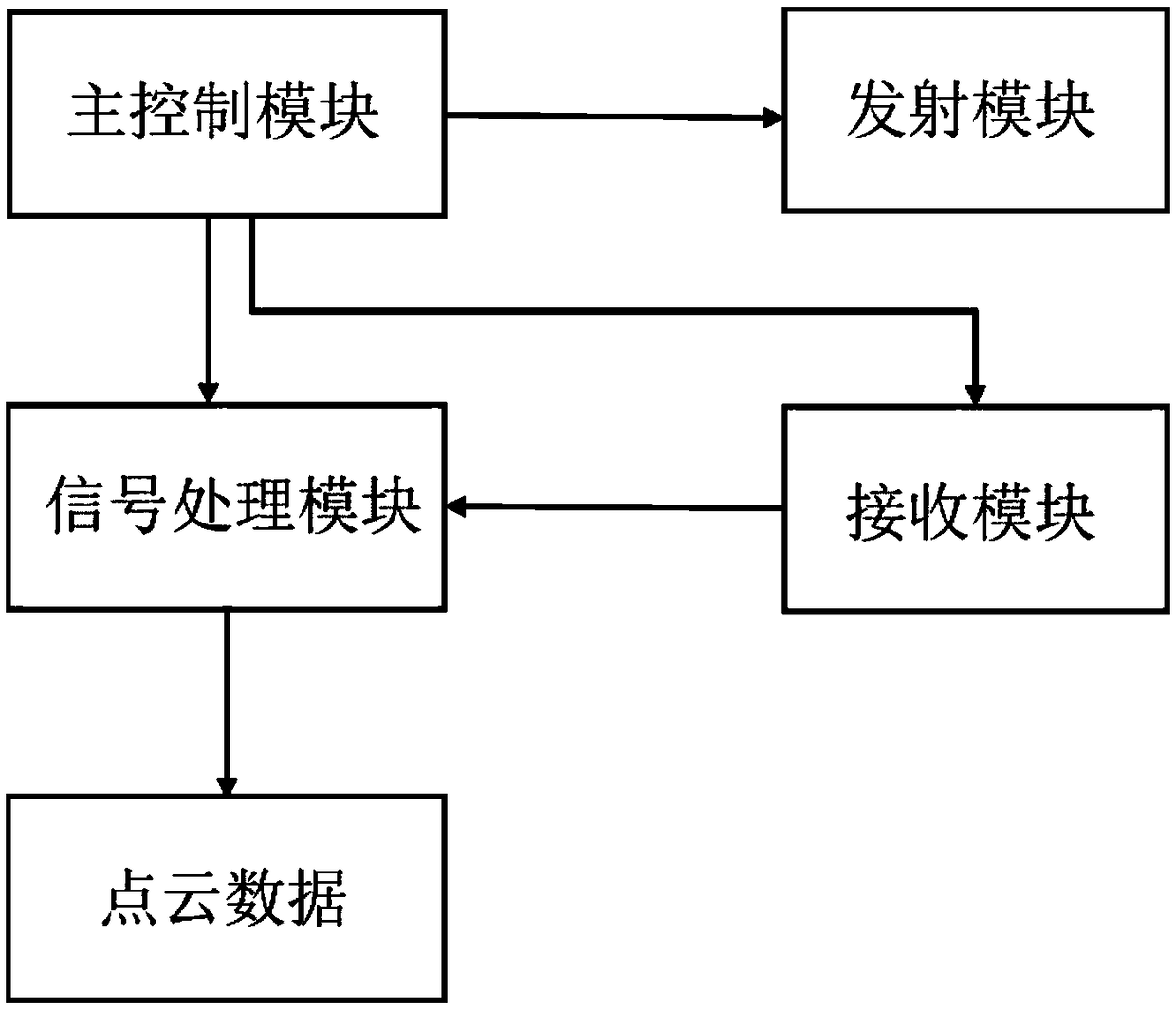
[0004] The purpose of the present invention is to propose a solid-state area laser radar device, through the setting of the fixed position of the transmitting module and the receiving module, it solves the problem that the traditional laser radar has a structure of mechanical rotation and an encoder, the structure is complicated, the space is large, and the assembly is difficult. The problem of numerous processes; through the setting of a single laser light source emitting laser light according to the set order and interval, and the structure of the area array photoelectric sensor controlling some or all pixels to receive the laser light emitted by the corresponding single laser light source, the detection of the laser radar device is expanded area, realizing long-distance large area array laser ranging, and providing an environmental detection device with better stability, better accuracy and higher efficiency that can cover a large area for a long time and a long distance

Method used


Image

  • Method for detecting solid-state laser radar device
  • Method for detecting solid-state laser radar device

Examples


Embodiment Construction

[0027] The technical solutions of the present invention will be further described below in conjunction with the accompanying drawings and through specific implementation methods.

[0028] It should be noted that, in the case of no conflict, the embodiments in the present application and the features in the embodiments can be combined with each other. The present invention will be described in detail below with reference to the accompanying drawings and examples.

[0029] In order to enable those skilled in the art to better understand the solution of the present application, the technical solution in the embodiment of the application will be clearly and completely described below in conjunction with the accompanying drawings in the embodiment of the application. Obviously, the described embodiment is only It is an embodiment of a part of the application, but not all of the embodiments. Based on the embodiments in this application, all other embodiments obtained by persons of ...


PUM


Abstract

Provided in the invention is a method for detecting a solid-state laser radar device. The method comprises: one single laser light source in an array laser device in a transmitting module works to emit detection light; step two, one column corresponding to the single laser light source working in the previous step in an array photoelectric sensor works; step three, the working column in the arrayphotoelectric sensor receives detection light reflected by a detected object; step four, a signal processing module reads electrical signal information received by the working column in the array photoelectric sensor, a signal processing module compares detection light emitted by the transmitting module with the detection light reflected by the detected object and received by the column in the receiving module to obtain a time difference, and a distance value is calculated based on a pulse flight time method; and step five, the previous four steps are repeated; a main control module controls different single laser light source in the array laser device to work when the step one is repeated each time; after each of all single laser light sources in the array laser device in the reflection module works at least once, one-frame point cloud distance data detection of the solid-state laser radar device is completed.

Description

technical field [0001] The invention relates to the technical field of laser radar measurement, in particular to a detection method of a solid-state area array laser radar device. Background technique [0002] The optical scanning ranging device is a device that uses collimated light beams to perform non-contact scanning ranging through time of flight (TOF for short), triangulation and other methods. At present, a common optical scanning ranging device includes: a light emitting module, an optical lens, and a chip for receiving and processing signals. The light emitting module emits light beams, and the optical lens is located on the optical path of the light emitting module. The collimated light beams are emitted to the surface of the object to be measured. When encountering obstacles, the light beams are reflected to the receiving chip, and the receiving chip transmits to the receiving space through measurement. The time, phase difference, and known speed of light can be ...

Claims


Application Information

Patent Timeline
IPC IPC(8): G01S7/484G01S7/486
CPCG01S7/484G01S7/486
Inventor 郑凯梁炳寅疏达李远
Owner BENEWAKE BEIJING TECH CO LTD
Learn More