Sectional tube nest cooling device in decomposing tank

A technology of cooling device and decomposition tank, which is applied in fixed tubular conduit components, alumina/aluminum hydroxide, heat exchanger types, etc., can solve the problems of easy abrasion of wide plates, complicated operation, and scarring of slurry. , to prevent the surface of the pipeline from scarring, reduce the lift, and reduce the amount of use

Inactive Publication Date: 2018-06-08
NORTHEASTERN UNIV ENG & RES INST CO LTD
View PDF4 Cites 3 Cited by
  • Summary
  • Abstract
  • Description
  • Claims
  • Application Information

AI Technical Summary

Problems solved by technology

[0003] At present, wide-channel plate heat exchangers are widely used for cooling outside the tank in the middle of the decomposition process. The wide-channel plate heat exchangers are more expensive, and during the cooling process, the slurry enters and exits the wide flow at a relatively high speed. The wide plate of the wide-channel plate heat exchanger is easy to be worn out, and the slurry is easy to scar and block the flow channel; and the existing cooling technology outside the tank must rely on the dump pump to transport the slurry to the The cooling process can only be completed in the wide channel plate heat exchanger outside the tank, and the operation is more complicated

Method used


Image

  • Sectional tube nest cooling device in decomposing tank
  • Sectional tube nest cooling device in decomposing tank
  • Sectional tube nest cooling device in decomposing tank

Examples


Embodiment 1

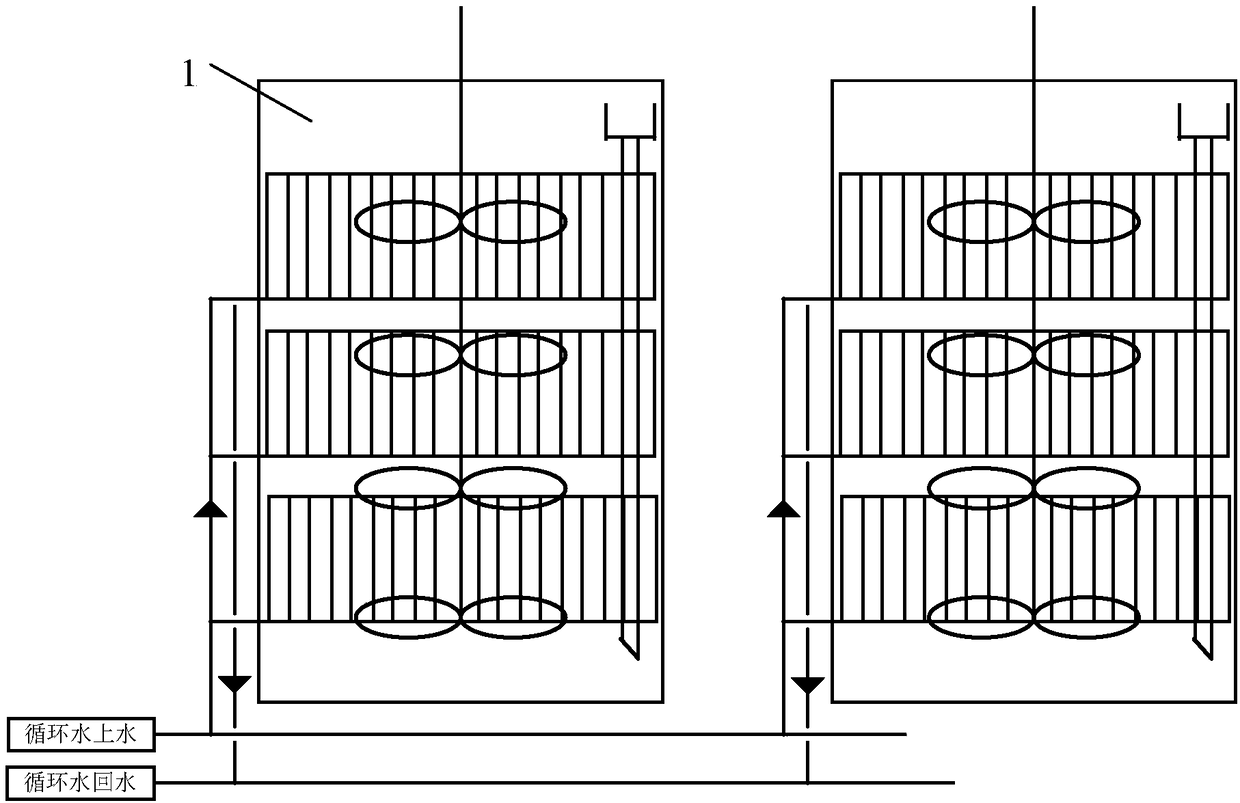
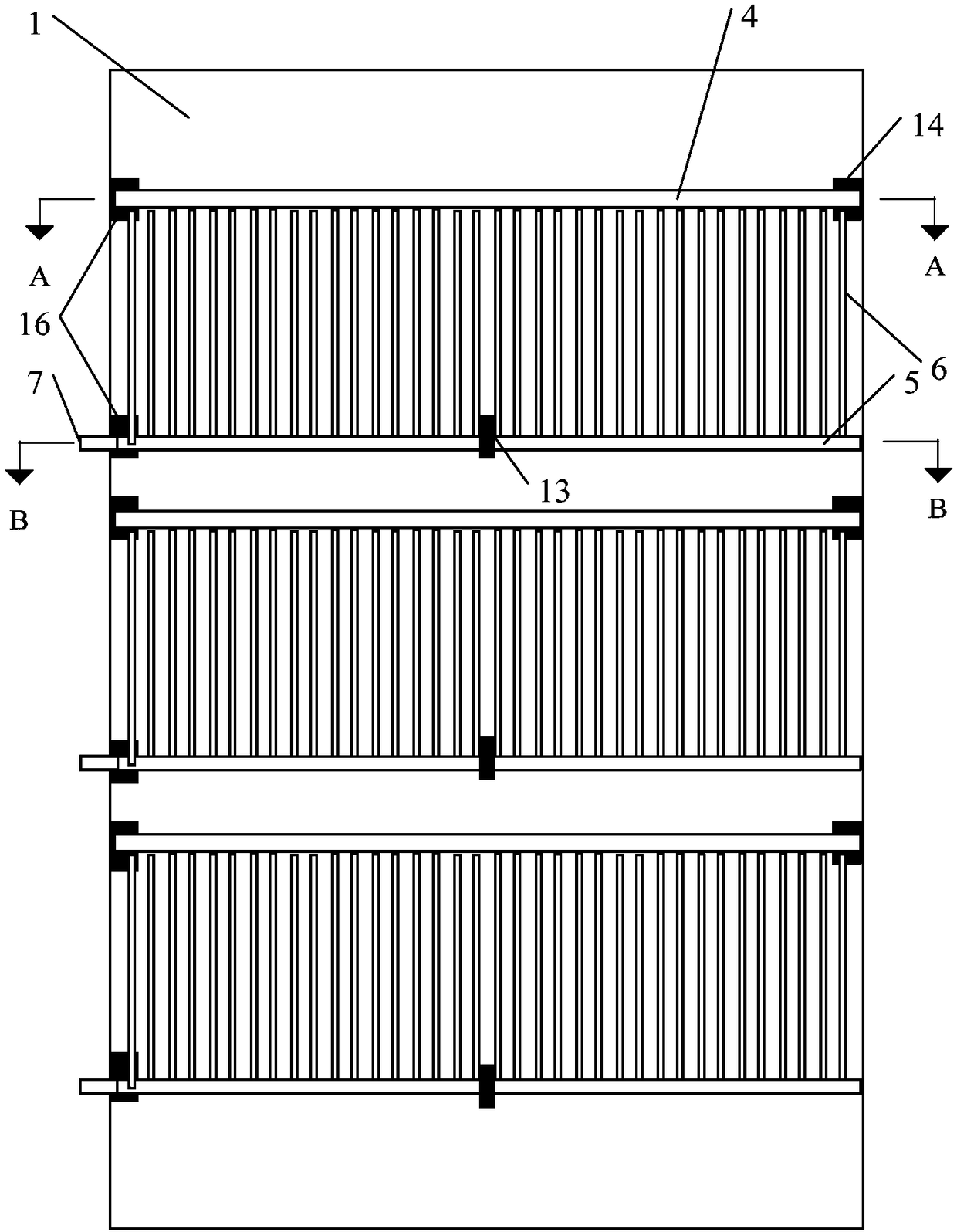
[0030] The segmented tube cooling device in the decomposition tank such as figure 2 As shown, three sections of cooling tubes are arranged in each decomposition tank 1, and the structure of a single decomposition tank is as follows image 3 As shown, its A-A surface structure is as Figure 4 As shown, the B-B surface structure is as Figure 5 As shown, the decomposition tank is divided into 3 sections of heat exchange areas from top to bottom, each section of heat exchange area is equipped with a section of cooling tubes, and each section of cooling tubes in the same decomposition tank is connected in parallel;

[0031] Each section of cooling tubes is composed of an upper ring tube 4, a lower ring tube 5, and a tube bundle between them. The tube bundle is composed of several vertical tubes 6 parallel to the axis of the decomposition tank. 4 is connected, and the bottom end is connected with the lower ring pipe 5; the water inlet 7 of each section of the cooling tube is con...

Embodiment 2

[0041] The segmented tube cooling device in the decomposition tank is the same as that in Embodiment 1, the difference is that:

[0042] (1) Each decomposition tank is equipped with 4 sections of cooling tubes, and the decomposition tank is divided into 4 sections of heat exchange zones from top to bottom;

[0043] (2) The height of the cooling tubes in each section is 5.25m, and the distance between the upper and lower adjacent cooling tubes is 0.75m; the heat exchange area of ​​each section is 300m 2 .


PUM


Abstract

The invention provides a sectional tube nest cooling device in a decomposing tank. The sectional tube nest cooling device is composed of multiple sections of cooling tube nests arranged in the decomposing tank, each decomposing tank is divided into multiple sections of heat exchange area from top to bottom, a section of cooling tube nest is arranged in each heat exchange area, and all sections ofcooling tube nests in the same decomposing tank are in parallel connection; each section of cooling tube nest is constituted by an upper annular pipe, a lower annular pipe and a tube nest cluster between the upper annular pipe and lower annular pipe, and the tube nest cluster is constituted by several vertical pipes parallel to the axis of the decomposing tank; water inlets of all sections of cooling tube nests are all communicated with a water inlet main pipe, and water outlets of all sections of cooling tube nests are all communicated with a water return main pipe. Decomposing slurry is directly cooled through sectional tube nest cooling devices in the decomposing tanks, the cooling procedure outside the tank is replaced, equipment investment and running cost are saved, and meanwhile, the work of the operating amount of workers and daily maintenance is reduced.

Description

technical field [0001] The invention belongs to the technical field of metallurgical equipment, and in particular relates to a segmented tube cooling device in a decomposition tank. Background technique [0002] Seed decomposition is one of the key processes in the alumina production process, which has a significant impact on the yield and quality of the product as well as technical and economic indicators; during the decomposition process, good quality aluminum hydroxide should be obtained, and at the same time, the decomposition of relatively high caustic molecules should be obtained The mother liquor, as the circulating mother liquor for leaching bauxite, constitutes a closed circuit of the Bayer process. [0003] At present, wide-channel plate heat exchangers are widely used for cooling outside the tank in the middle of the decomposition process. The wide-channel plate heat exchangers are more expensive, and during the cooling process, the slurry enters and exits the wid...

Claims


Application Information

Patent Timeline
Patent Type & Authority Applications(China)
IPC IPC(8): F28D7/16C01F7/02
CPCF28D7/16C01F7/02
Inventor 鄢艳岳玲黎娜史玉娟王宁
Owner NORTHEASTERN UNIV ENG & RES INST CO LTD
Why Eureka
Try Eureka