
Building material cutting device

A technology for cutting devices and building materials, applied in shearing devices, maintenance and safety accessories, shearing machine equipment, etc., can solve the problems of increasing labor burden, reducing cutting efficiency, falling, etc., to solve the burden of regularly replacing filters manually , The effect of improving cutting efficiency and avoiding loss

Active Publication Date: 2018-06-08
徐州天骋智能科技有限公司
View PDF4 Cites 3 Cited by
  • Summary
  • Abstract
  • Description
  • Claims
  • Application Information

AI Technical Summary

Problems solved by technology

[0002] Building material cutting is a relatively important part of the building material processing process. For some expensive building materials, the cutting process is also a wasteful process, because a lot of scraps are generated during the cutting process, and these scraps are often directly discharged. It is not only a waste for building material companies, but also a threat to human health, and it also pollutes the environment.
When the building material company gradually realized this problem, it also began to pay attention to this problem. When cutting building materials, they used pockets to collect them, but the effect was not good. They also used spraying to make the chips settle on the filter screen, and then collected them. The effect is effectively improved; however, as the debris on the filter gradually increases, the filtering effect becomes worse and worse, and after the debris accumulates on the filter for too long, some debris will fall from the mesh of the filter In addition, the chips on the edge of the filter screen will be released into the air after air drying, which requires manual replacement of the filter screen, thereby increasing the labor burden and reducing the cutting efficiency

Method used


Image

  • Building material cutting device
  • Building material cutting device

Examples


Embodiment Construction

[0014] The present invention will be described in further detail below by means of specific embodiments:

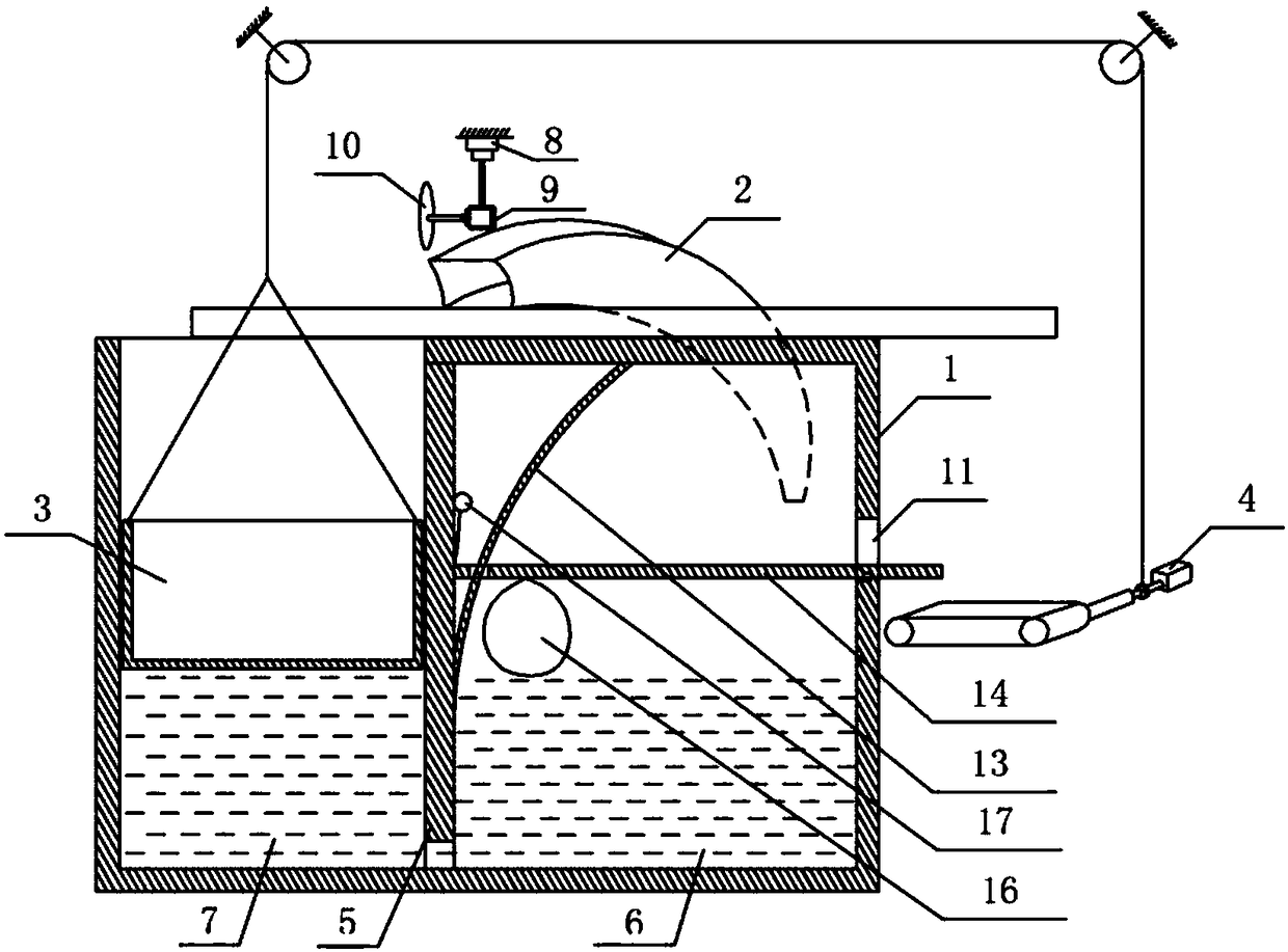
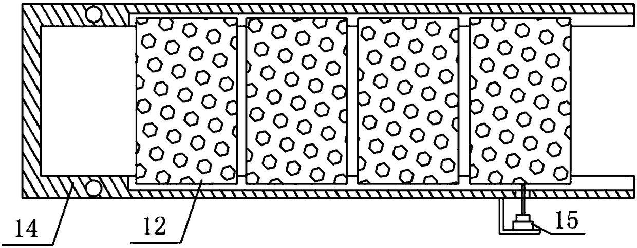
[0015] The reference signs in the drawings of the description include: support chamber 1, chip guide channel 2, collection box 3, servo motor 4, partition 5, chip collection chamber 6, collection chamber 7, lifting cylinder 8, stepping motor 9, Cutter 10, opening 11, square frame 12, arc bar 13, support bar 14, cylinder 15, air bag 16, switch 17, pay-off rack 18.

[0016] Such as figure 1 , 2 The building material cutting device shown includes a supporting chamber 1 , a cutting mechanism, a removing mechanism, a conveying mechanism, a rotating mechanism, a chip guide channel 2 , a collecting box 3 , a servo motor 4 and a partition 5 . The partition 5 divides the support chamber 1 into the chip collecting chamber 6 on the right and the collecting piece chamber 7 on the left. The bottom of the chip collecting chamber 6 and the collecting piece chamber 7 is connected. The...


PUM


Abstract

The invention relates to the field of building material processing, in particular to a building material cutting device. The device comprises a scrap collecting chamber, a workpiece collecting chamber, a moving mechanism, a conveying mechanism, a scrap guide channel, an arc-shaped rod, a supporting rod and a collecting box; an opening is formed in the side wall of the scrap collecting chamber, andthe supporting rod is in sliding connection with the arc-shaped rod; the supporting rod is hinged to the side wall of the scrap collecting chamber, and an air bag is arranged in the scrap collectingchamber; the conveying mechanism is arranged on the side close to the opening of the scrap collecting chamber, a servo motor is fixed to a rack, the servo motor is used for driving the conveying mechanism to rotate, and an output shaft of the servo motor is sleeved with a pay-off rack. When the technical scheme is used, a filter screen can be automatically replaced, the burden that the filter screen needs to be replaced manually is effectively solved, a square frame moves stably in the process of automatically replacing the filter screen so that the phenomenon that scraps fall off from the filter screen due to shaking can avoided, and meanwhile, the situations that the scraps fall off from meshes of the filter screen after being accumulated on the filter screen for too long time and are scattered into air after being air-dried are avoided.

Description

technical field [0001] The invention relates to the field of building material processing, in particular to a building material cutting device. Background technique [0002] Building material cutting is a relatively important part of the building material processing process. For some expensive building materials, the cutting process is also a wasteful process, because a lot of scraps are generated during the cutting process, and these scraps are often directly discharged. It is not only a waste for building materials companies, but also a threat to human health, and it also pollutes the environment. When the building material company gradually realized this problem, it also began to pay attention to this problem. When cutting building materials, they used pockets to collect them, but the effect was not good. They also used spraying to make the chips settle on the filter screen, and then collected them. The effect is effectively improved; however, as the debris on the filter...

Claims


Application Information

Patent Timeline
IPC IPC(8): B23D19/00B23Q11/00B23Q11/10
CPCB23D19/00B23Q11/005B23Q11/0067B23Q11/1069
Inventor 寇瑞东
Owner 徐州天骋智能科技有限公司
Learn More