Method for preparing high-performance composite strip through pulse current asymmetrical rolling
A technology of composite strip and pulse current, applied in the direction of metal rolling, etc., can solve the problems of difference, the interface bonding quality of metal composite plate is difficult to control, etc.
- Summary
- Abstract
- Description
- Claims
- Application Information
AI Technical Summary
Problems solved by technology
Method used
Image
Examples
Embodiment 1
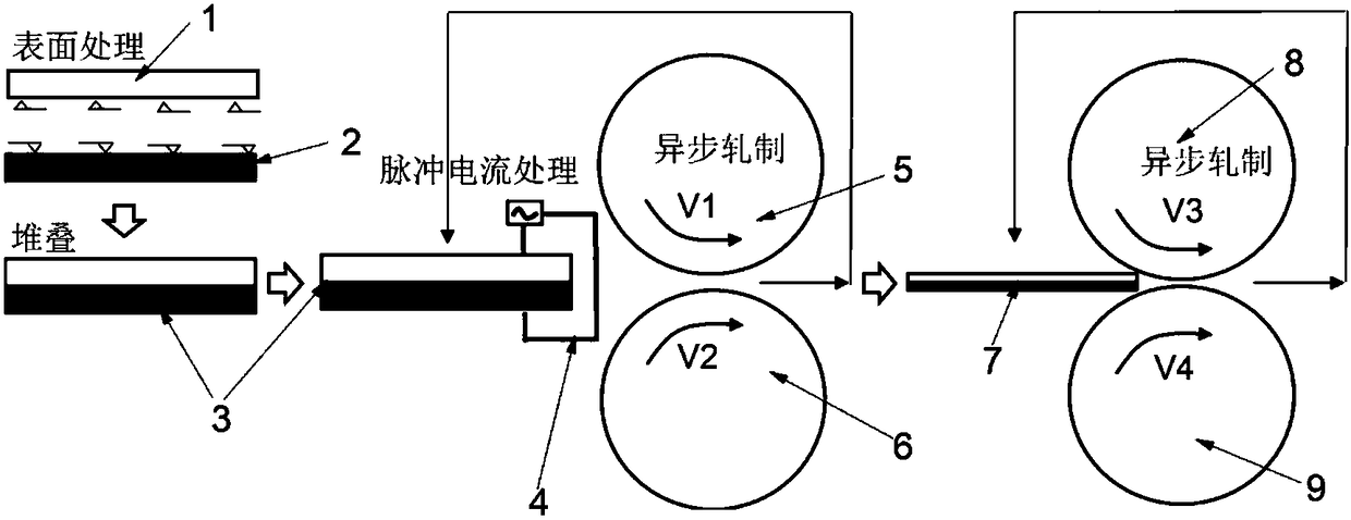
[0022] Example 1: Preparation of copper-aluminum composite strip, reference figure 1 .
[0023] The first step: take strip A1 and strip B2 as raw materials, strip A1 is copper strip, strip B2 is aluminum strip. The thicknesses of strip A1 and strip B2 before rolling were each 2 mm. The strips A1 and B2 were processed to have exactly the same dimensions of 1 m (length) x 0.2 m (width).
[0024] Step 2: Use a wire brush for surface treatment on strip A1 and strip B2 to remove surface oxides.
[0025] The third step: stacking the surface-treated surfaces of the strip A1 and the strip B2, wherein the surface-treated surfaces are opposite to each other, to obtain the A / B composite strip 3 .
[0026] The fourth step: at the rolling entrance, the pulse current device 4 is used to apply a pulse current to the A / B composite strip 3, so that discharge occurs in a local area on the surface of the material, and the surface metal is melted. During the rolling process, the pulse current...
Embodiment 2
[0030] Example 2: Preparation of titanium-aluminum composite strip, reference figure 1 .
[0031] The first step: take strip A1 and strip B2 as raw materials, strip A1 is a titanium strip, and strip B2 is an aluminum strip. The thicknesses of strip A1 and strip B2 before rolling were each 1.5 mm. The strip A1 and the strip B2 were processed to the exact same dimensions of 0.5 m (length) x 0.1 m (width).
[0032] Step 2: Use a wire brush for surface treatment on strip A1 and strip B2 to remove surface oxides.
[0033] The third step: stacking the surface-treated surfaces of the strip A1 and the strip B2, wherein the surface-treated surfaces are opposite to each other, to obtain the A / B composite strip 3 .
[0034] The fourth step: at the rolling entrance, the pulse current device 4 is used to apply a pulse current to the A / B composite strip 3, so that discharge occurs in a local area on the surface of the material, and the surface metal is melted. The pulse current power wa...
Embodiment 3
[0038] Example 3: Welding of the interface between ordinary carbon steel and ordinary carbon steel by pulse current plastic deformation
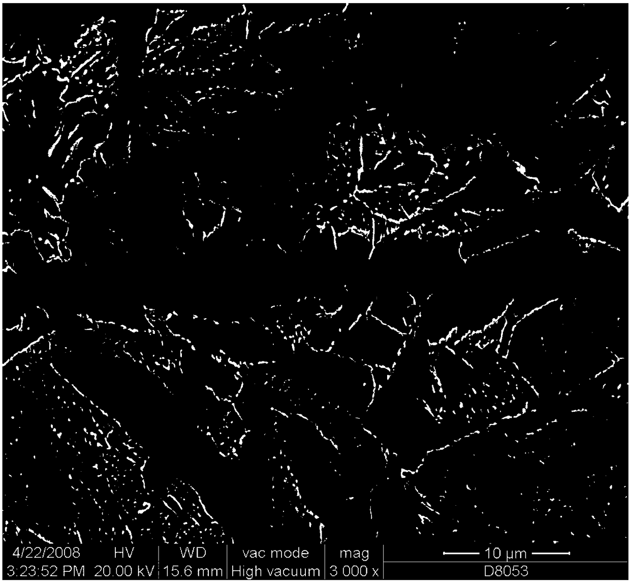
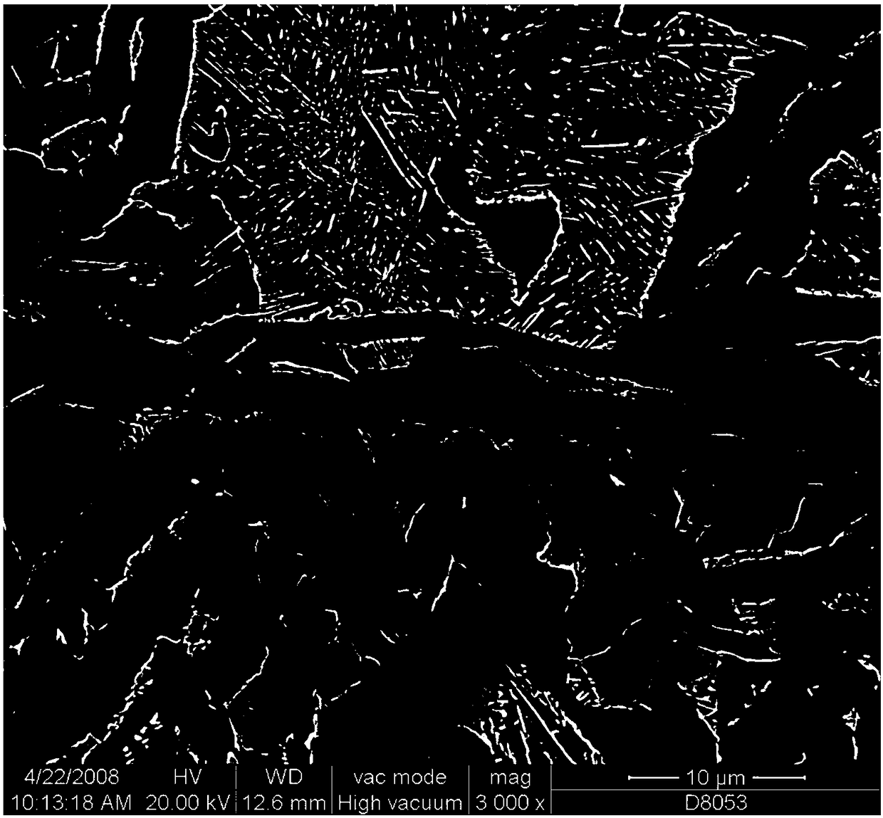
[0039] In order to verify the above method, a thermal simulation testing machine was used to conduct the experiment. The ordinary carbon steel was used as the raw material, the strip thickness was 4mm and 4mm, the pulse current power was 90KVA, and the reduction rate was 50%. The composite interface is fully metallurgically welded without any residual voids. like figure 2 Under the action of pulse current, part of the interface area is welded. image 3 The interface achieved complete metallurgical bonding after the application of a 50% reduction ratio after the action of the indicated pulse current.
PUM
| Property | Measurement | Unit |
|---|---|---|
| thickness | aaaaa | aaaaa |
| thickness | aaaaa | aaaaa |
| thickness | aaaaa | aaaaa |
Abstract
Description
Claims
Application Information
 - Generate Ideas
- Intellectual Property
- Life Sciences
- Materials
- Tech Scout
- Unparalleled Data Quality
- Higher Quality Content
- 60% Fewer Hallucinations
Browse by: Latest US Patents, China's latest patents, Technical Efficacy Thesaurus, Application Domain, Technology Topic, Popular Technical Reports.
© 2025 PatSnap. All rights reserved.Legal|Privacy policy|Modern Slavery Act Transparency Statement|Sitemap|About US| Contact US: help@patsnap.com


