
Signal covering method for WLAN (Wireless Local Area Network) base station based on sector switch

A signal coverage and sector technology, applied in wireless communication, space transmit diversity, advanced technology, etc., can solve the problem of the asymmetry of transmission power transmission link and reception link power, the inability to effectively increase the coverage, and the weak transmitter power. and other problems, to achieve sufficient time-division multiplexing, meet signal coverage requirements, and alleviate the effect of base station user collisions

Active Publication Date: 2018-06-05
FUJIAN SUNNADA NETWORK TECH CO LTD
View PDF10 Cites 2 Cited by
  • Summary
  • Abstract
  • Description
  • Claims
  • Application Information

AI Technical Summary

Problems solved by technology

Because traditional APs generally use the 2.4G frequency band for coverage, the transceiver module used for coverage is generally composed of a single wireless communication module and a single radio frequency unit. When the AP is interfered by a certain direction, it may affect the performance of the entire device. , and the anti-interference ability is weak; due to the characteristics of the network card chip itself, the capacity of traditional APs is limited. For densely populated areas, in order to meet the coverage requirements, more devices are needed, which will lead to the deterioration of the networking environment and increase the difficulty of networking. ;Traditional AP improves the anti-interference ability by increasing the power of the device, which is difficult to achieve in actual networking. High power will lead to the deterioration of the entire networking environment. The power will cause the problem of unequal power between the transmitting link and the receiving link, which cannot effectively increase the coverage

Method used


Image

  • Signal covering method for WLAN (Wireless Local Area Network) base station based on sector switch
  • Signal covering method for WLAN (Wireless Local Area Network) base station based on sector switch

Examples


Embodiment Construction

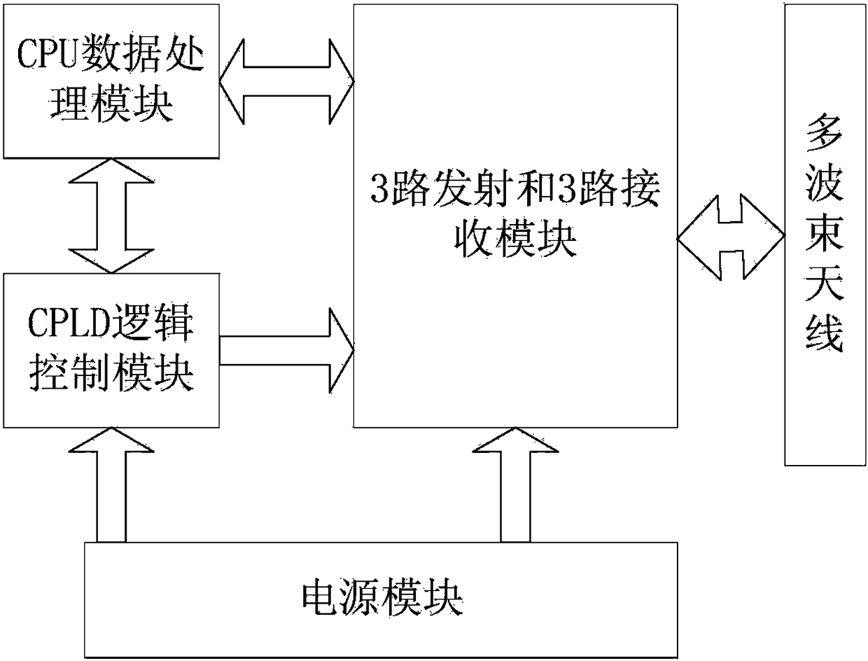
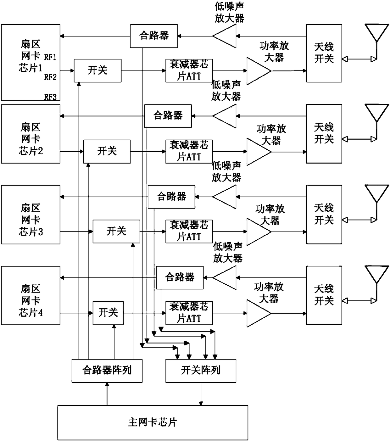
[0026] see figure 1 and figure 2 As shown, a kind of WLAN base station radio frequency implementation method based on multi-sector of the present invention, described method provides a CPU data processing module, CPLD logic control module, 3-way transmitting and 3-way receiving modules, multi-beam antenna, combiner Array, switch array and main network card chip; Described 3-way transmitting and 3-way receiving module comprise a plurality of sector modules, and each sector module structure is identical; Described method specifically comprises the following steps:

[0027] Step 1. After the multi-beam antenna of the WLAN base station receives the association request signal of the network card of the terminal;

[0028] Step 2, the sector network card chip of each sector module sends the data received by different sector modules to the corresponding sector network card chip by controlling the switch and antenna switch in the sector module;

[0029] Step 2, the sector network ca...


PUM


Abstract

The invention provides a realization method for radio frequency of a WLAN (Wireless Local Area Network) base station based on multiple sectors. The WLAN base station adopts a multi-sector switch mechanism; each sector corresponds to one group of 3*3 MIMO (Multiple Input Multiple Output); sector network card chips are mainly used as receivers, correspond to all the sectors and are responsible for receiving corresponding sector data; a main network card is used as a transmitting chip for transmitting a management frame and a data frame to the sectors and also can be used for receiving any one link data; by multi-sector coverage, multi-channel transceiving and more sufficient time sharing multiplex, the number of concurrent users is greatly increased; the sector network cards are mainly usedas the receivers, and receiving of all the sectors is non-interfering, so that the antijamming capability of the base station is improved; when users in different sectors collide, one sector is only transmitted and further user collision of the base station is relieved; by adopting a multi-sector and multi-transceiving mechanism, an optimal path can be effectively selected, the signal processing capacity is improved and the covering range is widened.

Description

[0001] This case is a divisional application based on the patent application with the filing date of 2014.09.16, the application number of 201410471006.7, and the title of "A Method for Implementing Radio Frequency of a WLAN Base Station Based on Multi-sectors". technical field [0002] The invention relates to the technical field of communication equipment, in particular to a multi-sector-based WLAN base station radio frequency implementation method. Background technique [0003] WLAN base stations use electromagnetic waves to send and receive data in the air, effectively solving the problem of network channel connectivity that is not easy to achieve by wired methods. Due to the advantages of high mobility, low price, easy expansion, and high transmission rate, WLAN technology has been widely used at present. It is widely used in the field of wireless extension. [0004] With the continuous advancement of my country's rural information construction, strengthening rural broa...

Claims


Application Information

Patent Timeline
Patent Type & Authority Applications(China)
IPC IPC(8): H04B7/06H04W16/24H04W40/02H04W84/12
CPCY02D30/70
Inventor 柯友艺
Owner FUJIAN SUNNADA NETWORK TECH CO LTD
Learn More