Bicycle freewheel
A bicycle and flywheel technology, applied in flywheels, vehicle parts, mechanical equipment, etc., can solve the problems of slow rotation speed of flywheels, achieve the effects of increasing the speed of rear wheels, improving sensitivity, and reducing kinetic energy loss
- Summary
- Abstract
- Description
- Claims
- Application Information
AI Technical Summary
Problems solved by technology
Method used
Image


Examples
no. 1 example
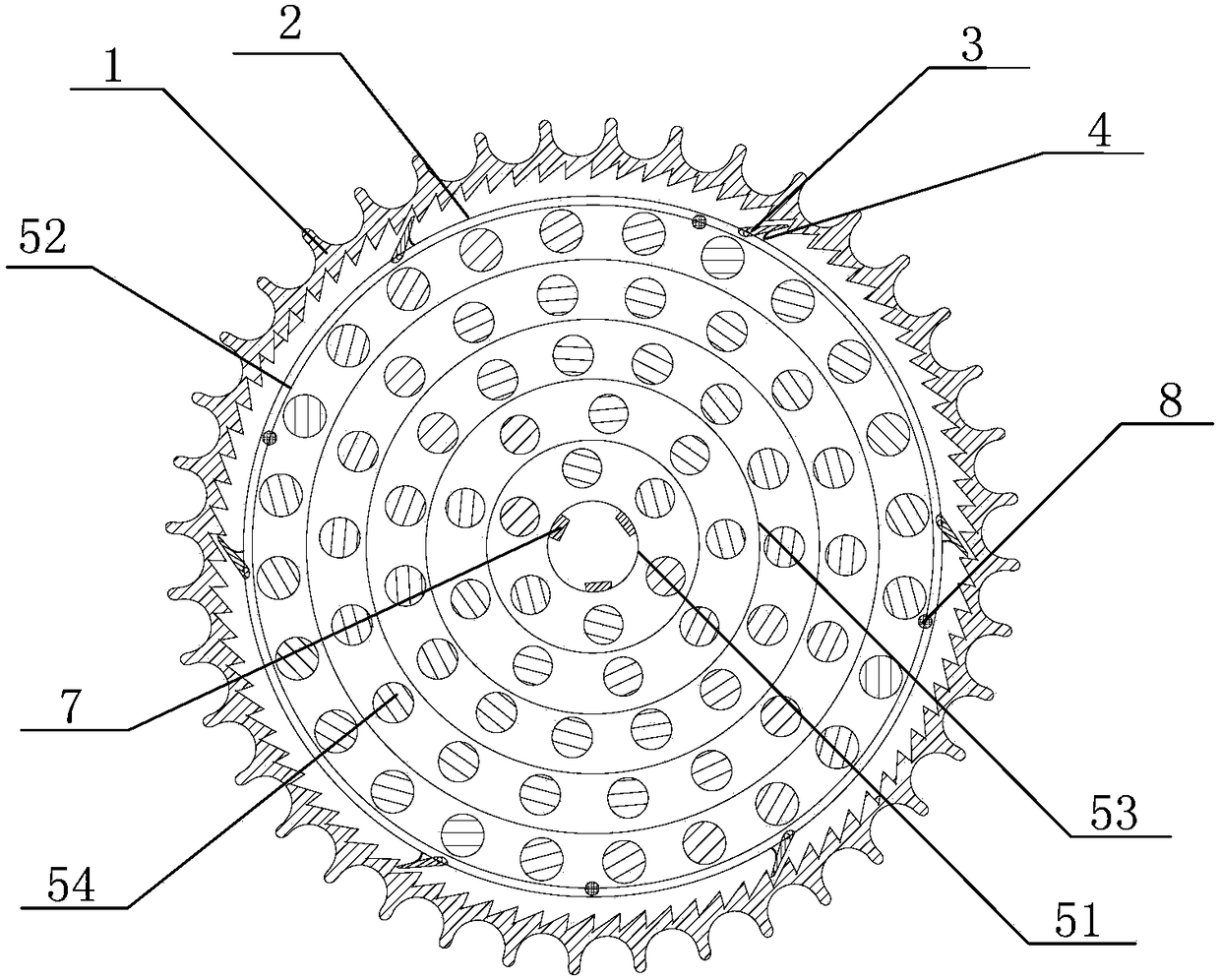
[0053] figure 1 It is a schematic view showing the internal structure of the first embodiment of the bicycle flywheel provided by the present invention. figure 2 It is a schematic diagram showing the external structure of the first embodiment of the bicycle flywheel provided by the present invention.
[0054] Such as figure 1 and figure 2 As shown, the bicycle flywheel includes a flywheel body.
[0055] Wherein, the flywheel body includes a jacket 1, a flying core 2, a jack 3, a jack spring 4 and a multilayer rolling bearing.
[0056] details as follows:
[0057] The outer casing 1 and the flying core 2 are respectively formed into rings with respective assembly holes, and the flying core 2 is embedded in the assembly hole of the outer casing 1; the outer ring surface of the outer casing 1 is evenly distributed with external teeth for connecting with the chain , there are ratchets evenly distributed on the inner ring surface of the jacket 1; the jack 3 is a pawl hinged ...
no. 2 example
[0067] On the basis of the first embodiment, along the direction extending from the top of the flywheel body to the bottom of the flywheel body, the external teeth and the ratchet teeth respectively have at least two layers.
[0068] For example, along the direction extending from the top of the flywheel body to the bottom of the flywheel body, the outer teeth and the ratchet teeth respectively have two layers, and correspondingly, the positions of the jack and the jack spring are set.
[0069] It should be noted that, in the above-mentioned specific embodiment, the number of jacks on each layer can be 6 as shown in the figure or 2, 3, 7, 8 or any other greater than 1, and An integer not greater than the number of ratchets.
[0070] Moreover, in the above specific embodiments, there is no limitation on the form of the rolling elements, which may be in various forms such as balls, needle rollers, or rolling elements of rolling mills.
[0071] The structure of the two specific ...
no. 1 example
[0073] The installation structure of the first embodiment
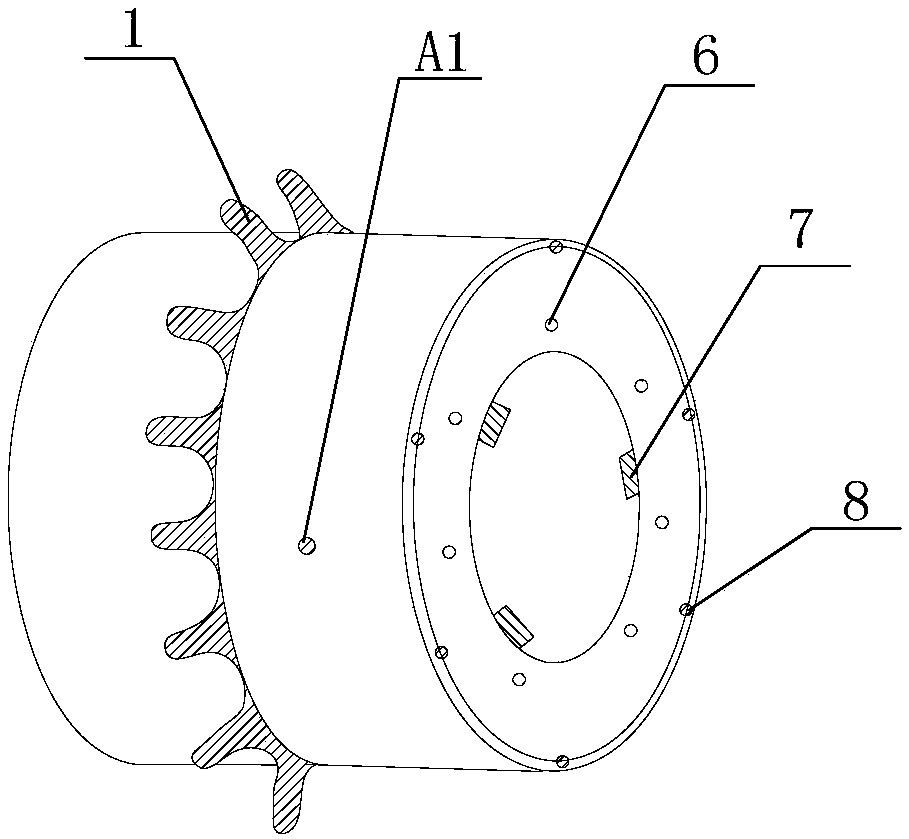
[0074] image 3 It is a schematic view showing the installation structure of the first embodiment of the bicycle flywheel provided by the present invention.
[0075] Such as image 3 As shown, the bicycle flywheel is installed on a tire, the tire installation point of the bicycle flywheel is represented by A1, the multilayer rolling bearing of the bicycle flywheel is installed in the middle of the tire, and the outer layer axle sleeve 52 of the multilayer rolling bearing is provided with a brake Sheet mount point 8.
[0076] The second embodiment installation structure one
[0077] Figure 4 It is the mounting structure one of the second embodiment representing the bicycle flywheel provided by the present invention.
[0078] Such as Figure 4 As shown, the bicycle flywheel is installed on a tire, and the tire installation point of the bicycle flywheel is represented by A2. The multi-layer rolling bearing of the ...
PUM
 Abstract
Description
Claims
Application Information
 - Generate Ideas
- Intellectual Property
- Life Sciences
- Materials
- Tech Scout
- Unparalleled Data Quality
- Higher Quality Content
- 60% Fewer Hallucinations
Browse by: Latest US Patents, China's latest patents, Technical Efficacy Thesaurus, Application Domain, Technology Topic, Popular Technical Reports.
© 2025 PatSnap. All rights reserved.Legal|Privacy policy|Modern Slavery Act Transparency Statement|Sitemap|About US| Contact US: help@patsnap.com