Novel transient recording fault indicator

A fault indicator and transient recording technology, applied in the direction of the measuring device shell, etc., can solve the problems of inconvenient plugging and unplugging, easy damage, and failure to achieve rapid detection, so as to reduce the possibility of assembly operation errors and ensure current detection Accuracy, the effect of good waterproof and dustproof function

Active Publication Date: 2018-06-01
宁波泰丰源电气有限公司
View PDF13 Cites 0 Cited by
  • Summary
  • Abstract
  • Description
  • Claims
  • Application Information

AI Technical Summary

Problems solved by technology

[0003] At present, the waterproof methods of the transient state recording type fault indicators currently available on the market are mainly screw-tight seals and screw-tight seals. The structure is complex and it is difficult to lock the sealing device, and the waterproof effect is poor.
The transient recording type fault indicator is glued and fixed in the main body, and the magnetic attraction of the moving plate is assembled and fixed in the moving plate assembly. This treatment method is likely to cause misoperation during the assembly operation of workers.
The suction surface of the magnetic suction is reversed, which leads to the failure of the suction. Since the magnetic suction in the main body is glued and fixed, it is very troublesome to disassemble. The electric field sensing sheet is generally made of stainless steel. When inducing the electric field, a wire is needed to bend the electric field sensing sheet of the thin sheet into contact with the wire to induce the electric field. Since the width of the electric field sensing sheet is generally small, the sampled current is relatively weak, which is beneficial to the later stage. The signal processing is unfavorable; in the process of moving location and transportation, the permalloy magnetic core in the existing fault indicator has no external protection, which is easy to be damaged, resulting in a decrease in the power-taking capacity of the magnetic core. When detecting the current, the plug-in terminals used are inconvenient to plug and unplug, and cannot achieve the effect of rapid detection

Method used


Image

  • Novel transient recording fault indicator
  • Novel transient recording fault indicator
  • Novel transient recording fault indicator

Examples


Embodiment Construction

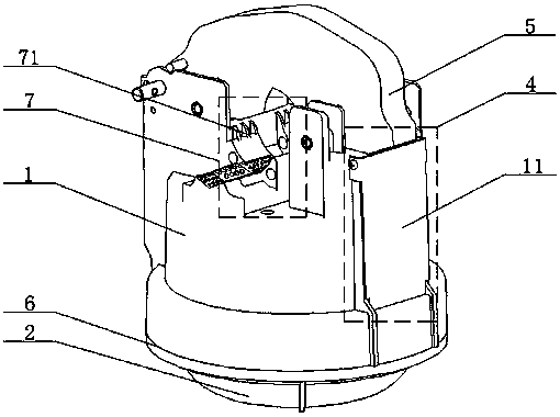
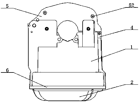
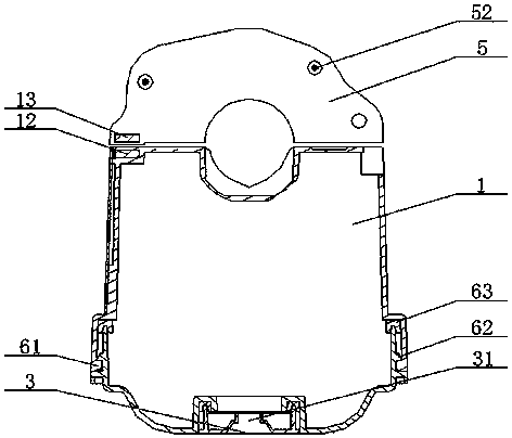
[0024] see Figure 1-Figure 7 As shown, the technical solution adopted in this specific embodiment is: it includes a main body 1, a transparent cover 2, a decorative plate 3, a magnet placement device 4, a magnetic core protective cover 5, a rotary buckle sealing device 6, an induction sheet 7, Test terminal 8; the bottom surface of the main body 1 is connected with a transparent cover 2, and the decorative plate 3 is set at the connection position between the transparent cover 2 and the main body 1; the inside of the main body 1 is provided with a magnet placement device 4, and the magnetic core protective cover 5 is set on the main body 1; the position connecting the main body 1 and the transparent cover 2 is provided with a turnbuckle sealing device 6; At the position on the main body 1, when using the new type of transient recorder type fault indicator for current fault detection, the test terminal 8 can be installed or disassembled on the main body 1, and the test termina...


PUM


Abstract

The invention provides a novel transient recording fault indicator, and relates to the field of circuit fault detection tools. A transparent cover is connected on the surface of the bottom part of theincluded body of the novel transient recording fault indicator. A decoration plate is arranged on the connecting position of the transparent cover and the body. The body is internally provided with aclosing magnet placing device. A magnetic core protective sleeve is arranged on the upper part of the body. The connecting position of the body and the transparent cover is provided with a screwed buckling sealing device. An induction piece is arranged on the upper part of the body and arranged on the same surface with the magnetic core protective sleeve. A test terminal is arranged on the position of the decoration plate on the body. With application of the technical scheme, the beneficial effects are that the novel transient recording fault indicator has great waterproof and dustproof functions, the movable plate magnetic catch can be conveniently detached, the possibility of assembling misoperation can be reduced, the induction piece is made of rubber material and later signal processing is facilitated, the power taking capacity of the permalloy can be protected, blind detection operation can be conveniently performed for blind detection of the production, the current detection accuracy can be guaranteed and the fault section can be rapidly located.

Description

technical field [0001] The invention relates to the field of circuit fault detection tools, in particular to a novel transient wave recording type fault indicator. Background technique [0002] Transient wave recording type fault indicator can accurately detect line fault type and quickly locate the fault section through accurate measurement of line current and high-speed wave recording. [0003] At present, the waterproof methods of the transient state recording type fault indicators currently available on the market are mainly screw-tight seals and screw-tight seals, which are complex in structure and difficult to lock the sealing device, and the waterproof effect is poor. The transient recording type fault indicator is glued and fixed in the main body, and the magnetic attraction of the moving plate is assembled and fixed in the moving plate assembly. This treatment method may easily lead to misoperation during the assembly operation of workers. The suction surface of th...

Claims


Application Information

Patent Timeline
IPC IPC(8): G01R1/04
CPCG01R1/04
Inventor 袁郭竣王马军张泳
Owner 宁波泰丰源电气有限公司
Why Eureka
Try Eureka