


Quick Research
Generate reliable direction feasibility study reports for your R&D in just a few steps.

Technical Q&A
Discover and master advanced knowledge NOW. Basics, ideas, possibilities, all at once.

Find Solutions
As an expert in R&D theories, this can generate solutions to your technical problems instantly.

Evaluate Feasibility
Analyze your overall solution with one click, know your potential R&D risks in advance.

Monitor Landscape
Get weekly tech updates, stay abreast of the latest tech innovations and key insights.
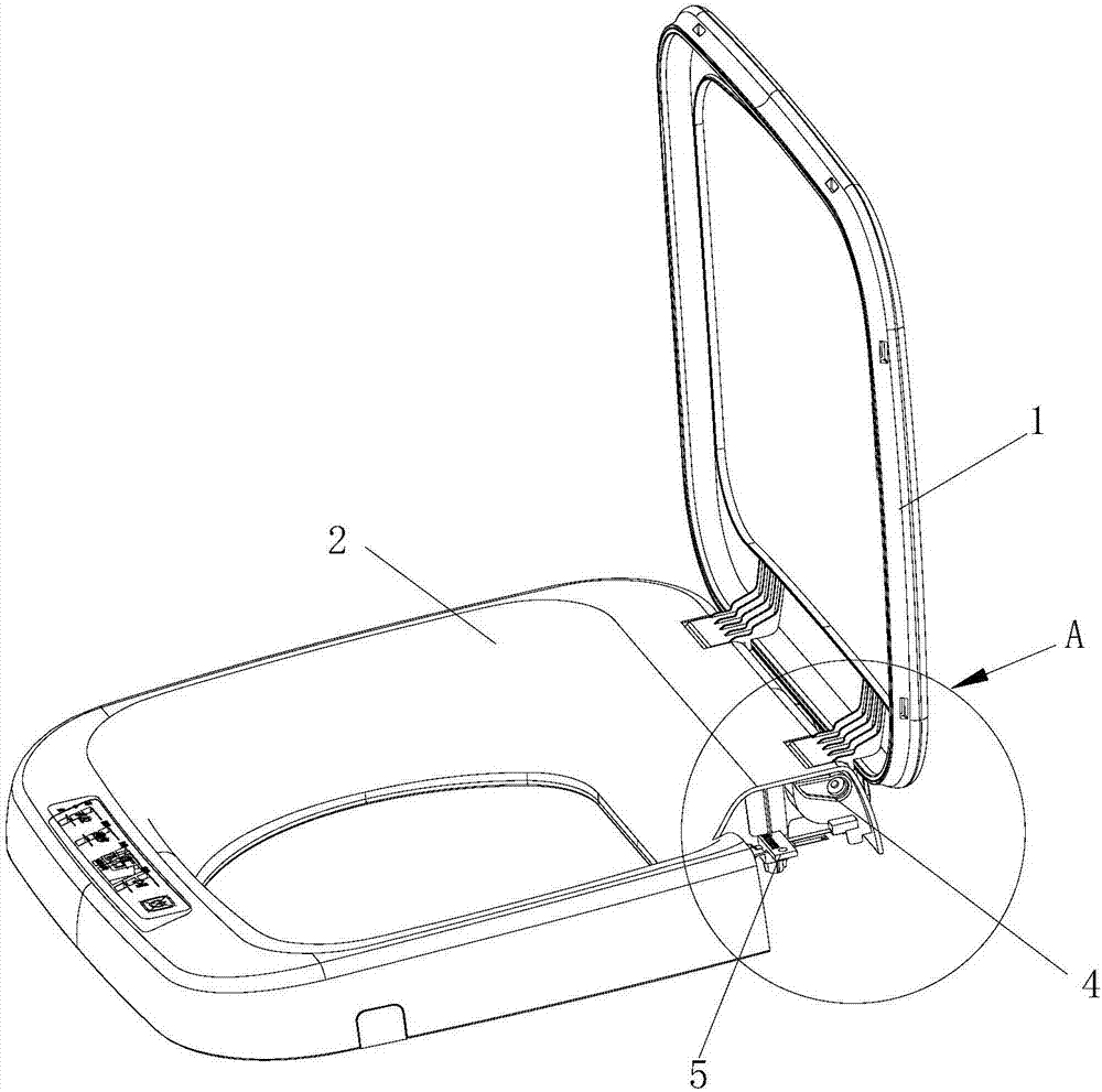
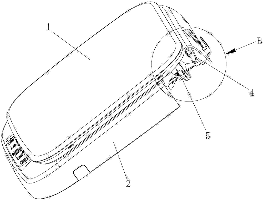
Safety control structure for opening and closing of upper cover
A safety control and safety switch technology, applied in textiles and papermaking, other washing machines, household appliances, etc., can solve the problems of poor dustproof effect and space occupation, achieve stable operation, compact installation structure, and reduce material costs
- Summary
- Abstract
- Description
- Claims
- Application Information
AI Technical Summary
Problems solved by technology
Method used
Image

Examples
Embodiment 1
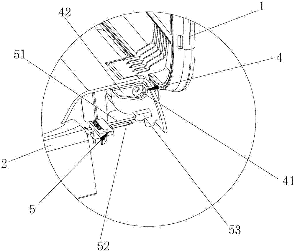
[0038] Such as figure 2 and Figure 4 As shown, the safety switch of the present invention is a leaf switch 5, including a moving reed 51 and a static reed 52, the moving reed 51 is arranged above the static reed 52, and the toggle part 4 is located above the moving reed 51 .
[0039]Further, one end of the moving spring 51 extends below the rotating shaft 3 , and the end is provided with a supporting member 53 that is in contact with the toggle part 4 . The supporting member 53 bears the downward pressure of the toggle part 4 , and controls the action of the movable reed 51 connected thereto according to the change caused by the pressure, and contacts and connects with the static reed 52 downward. The design of the supporting member increases the contact area with the toggle part compared with the movable reed, so as to prevent the dislocation of the toggle from causing the inability to contact the movable reed, thereby failing to realize the safety control of opening the ...
Embodiment 2
[0041] Such as figure 2 and Figure 4 As shown, the toggle part 4 of the present invention includes a connecting piece 41 and a toggle piece 42, wherein the connecting piece 41 is integrally connected with the rotating shaft 3, one end of the toggle piece 42 is connected with the connecting piece 41, and the other end is a control brake. The reed 51 acts to connect / disconnect the movable end 43 with the static reed 52 .
[0042] Further, the toggle piece 42 is provided with a guide surface 44 that guides the movable end 43 to move smoothly between the front of the support piece 53 and the top of the support piece 53. The guide surface 44 is an inclined surface and is located on the movable end 43 of the toggle piece. The side opposite to the direction where the upper cover 1 is located. Since the upper cover and the safety switch are both arranged on the front side of the rotating shaft, and the toggle part and the upper cover rotate in the same direction, when the upper co...
Embodiment 3
[0044] Such as Figure 5 and Figure 6 As shown, the connecting piece 41 described in this embodiment is sheathed on the outer periphery of the rotating shaft 3 , and the connecting piece 41 is keyed to the rotating shaft 3 .
[0045] Further, the connecting piece 41 is arranged at one end of the rotating shaft 3, and the other end of the rotating shaft 3 is inserted into the hinge part between the upper cover 1 and the disk base 2, and the connection part between the connecting piece 41 and the rotating shaft 3 is cylindrical, corresponding to inserting the disk The hinged part of the seat is free to rotate with the hinged part of the disc seat.
[0046] Alternatively, the toggle part 4 and the rotating shaft 3 are integrally structured. Alternatively, the toggle part 4 is fixedly connected to the rotating shaft 3 through pins, bolts, screws or other structures capable of fastening.
PUM
 Abstract
Description
Claims
Application Information
 - R&D Engineer
- R&D Manager
- IP Professional
- Industry Leading Data Capabilities
- Powerful AI technology
- Patent DNA Extraction
Browse by: Latest US Patents, China's latest patents, Technical Efficacy Thesaurus, Application Domain, Technology Topic, Popular Technical Reports.
© 2024 PatSnap. All rights reserved.Legal|Privacy policy|Modern Slavery Act Transparency Statement|Sitemap|About US| Contact US: help@patsnap.com