Steel lifting device

A technology of supporting steel and driving device, which is used in the attachment of sawing machines, large fixed members, metal sawing equipment, etc., to achieve the effect of strong applicability, wide product coverage and simple structure

Pending Publication Date: 2018-06-01
HUATIAN NANJING ENG & TECH CORP MCC
View PDF10 Cites 2 Cited by
  • Summary
  • Abstract
  • Description
  • Claims
  • Application Information

AI Technical Summary

Problems solved by technology

Although this method is simple in structure and has certain effects, it cannot fundamentally eliminate the problem of head bending and downward drooping.

Method used


Image

  • Steel lifting device
  • Steel lifting device
  • Steel lifting device

Examples


Embodiment Construction

[0020] The present invention will be further described below in conjunction with the accompanying drawings.

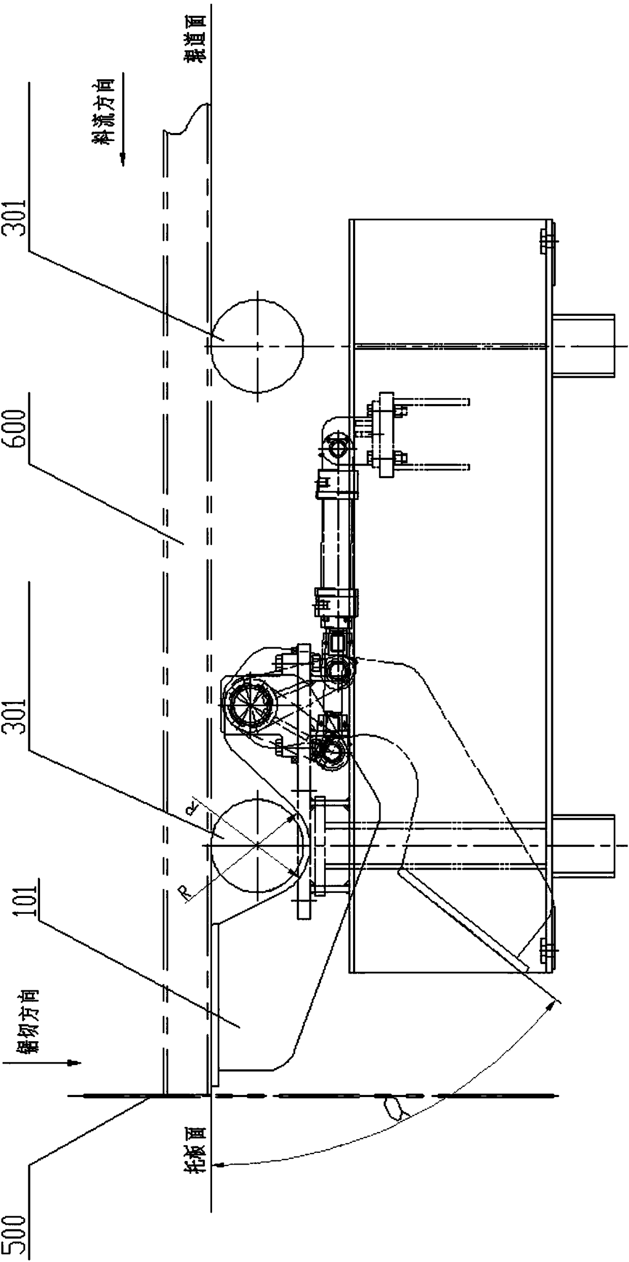
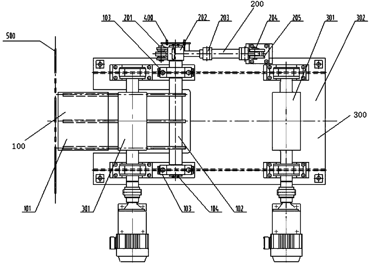
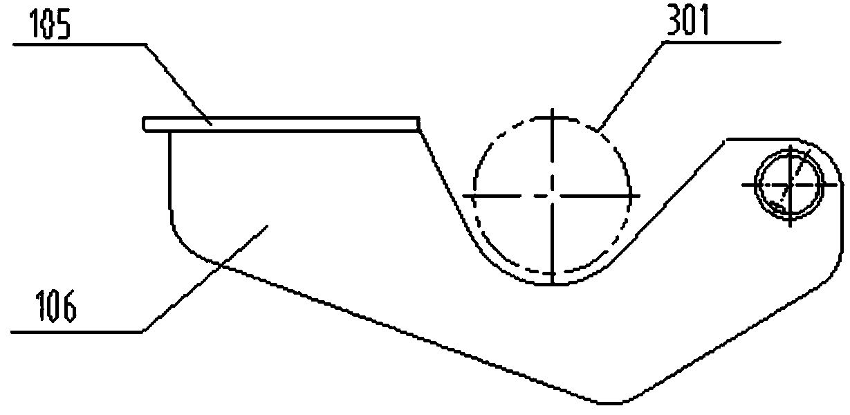
[0021] Such as figure 1 , figure 2 As shown, the whole set of steel supporting device is composed of four major parts: a supporting plate device 100 , a driving device 200 , a steel supporting roller table 300 , and a detection device 400 . The pallet device 100 is made up of a pallet 101 , a pallet support shaft 102 , and a bearing seat 103 , and the pallet device is fixed on the roller frame 302 by connecting bolts. The roller table frame 302 and two roller assemblies 301 form the supporting steel roller table 300, and the roller assembly 301 is fixed on the roller table frame 301 by bolts. The driving device 200 is connected with the pallet device 100 and is arranged on the roller frame 302 ; the detection device 400 is arranged at the connection between the pallet device 100 and the driving device 200 , and transmits signals to control the driving device 200 to ...


PUM


Abstract

The invention discloses a steel lifting device. The steel lifting device comprises a lifting plate device, a driving device, a steel lifting roller track and a detecting device; and the detecting device can transmit a signal to control the driving device to lift up or put down the lifting plate device. According to the steel lifting device, rolled pieces which are suspended out of the roller trackcan be lifted up and be kept at the same plane with the roller track, the problems of bending and slouch head of the rolled pieces due to sawing-cutting force in the sawing-cutting process are reduced maximally, and safety in the rolling process is greatly improved; and the structure is simple, applicability is high, the product coverage range is wide, and the steel lifting device can be appliedto different types and specifications of rolled pieces such as profile steel, big sticks and other profiles, and can be widely used in mechanical equipment with the same functional requirements.

Description

technical field [0001] The invention relates to a steel rolling system in the metallurgical industry, in particular to a steel supporting device. Background technique [0002] The equipment in the rolling mill area is an important process equipment in the steel rolling production line, and its function is to roll and form the billet. For the section steel rolling process, two billet cutting machines are generally installed, and the billet is first subjected to repeated rough rolling for several passes, and then enters the finish rolling mill for continuous rolling. Before entering the finishing mill, it is necessary to set up a hot saw, the purpose of which is to cut the head of the rolled piece that has been roughly rolled by the billet mill, and cut off the deformed part of the head due to repeated rolling by the billet mill. , so that the finishing mill can smoothly bite the rolled piece into the roll for continuous rolling. As an auxiliary device for hot saws and finis...

Claims


Application Information

Patent Timeline
Patent Type & Authority Applications(China)
IPC IPC(8): B23D59/00B23Q1/76B23Q17/00
CPCB23D59/00B23Q1/76B23Q1/763B23Q17/00
Inventor 阮祥伟刘德江杨文果
Owner HUATIAN NANJING ENG & TECH CORP MCC
Why Eureka
Try Eureka