
Micromechanical component and suitable method for its manufacture

a micromechanical and component technology, applied in the direction of fluid pressure measurement, fluid pressure measurement by electric/magnetic elements, instruments, etc., can solve the problems of complex method for nonlinear behavior correction, to date, nonlinear behavior has been considered the main disadvantage of capacitive relative pressure sensors, etc., to achieve cost-effectiveness, improve linear behavior, and process simple and reliable

Active Publication Date: 2006-08-03
ROBERT BOSCH GMBH
View PDF3 Cites 36 Cited by
  • Summary
  • Abstract
  • Description
  • Claims
  • Application Information

AI Technical Summary

Benefits of technology

[0007] The invention provides a micromechanical component comprising: a substrate (1), of which at least some regions are conductive; an elastically deflectable diaphragm (M), of which at least some sections are conductive, and which arches over a front side (V) of the substrate (1) and is electrically insulated from the substrate (1), the diaphragm (M) having an inner region (I; I′) and an edge region (RB; RB′); and a hollow space (H), which is provided between the substrate (1) and the diaphragm (M); the inner region (I; I′) having a cross-section that is modified in comparison with the edge region (RB; RB′), which means that the bending of the inner region (I; I′) is less than that in the case of an identical cross-sectional area. The micromechanical component of the invention and the manufacturing method according to the invention have the advantage, that they provide a simple and reliable process for manufacturing micromechanical components, in particular capacitive pressure sensors, which may be implemented in a particularly cost-effective manner. The present invention renders possible, in particular, a capacitive relative-pressure sensor, which has a markedly improved linear behavior due to the manner of manufacturing according to the present invention.
[0008] The idea forming the basis of the present invention is that the cross section or layer thickness of some regions of the diaphragm is modulated, i.e. a more complex diaphragm structure is provided, which includes sections that take part less or do not take part at all in the deflection. Critical process steps are avoided to the greatest possible extent, as well as exotic process steps, such as pasting wafers onto substrate wafers, or the like. The core part of the process is trench-etching from the back side of the wafer, in conjunction with subsequent sacrificial-layer etching under the future diaphragm, the sacrificial-layer etching having an extremely high selectivity. Without further measures to protect the surrounding silicon, this very high selectivity allows the sacrificial-layer etching technique to be implemented without attacking the existing silicon structures, which markedly simplifies the entire process again.

Problems solved by technology

Since the cross-section of the diaphragm as a whole follows a curved bending line in response to the application of pressure, curved regions of the diaphragm outside of its center or center region contribute more and more to the generation of the measured signal, which results in nonlinearity, i.e. a curve of the reciprocal capacitance that no longer runs proportionally to the pressure.
The correction of nonlinearity is a complicated method, since in this method, a correction data set, via which numerical linearization of the data supplied by the sensor is subsequently possible and implementable, must be stored for each sensor element.
Thus, nonlinear behavior has been considered to be, to date, the main disadvantage of capacitive relative-pressure sensors.

Method used


Image

  • Micromechanical component and suitable method for its manufacture
  • Micromechanical component and suitable method for its manufacture
  • Micromechanical component and suitable method for its manufacture

Examples


Embodiment Construction

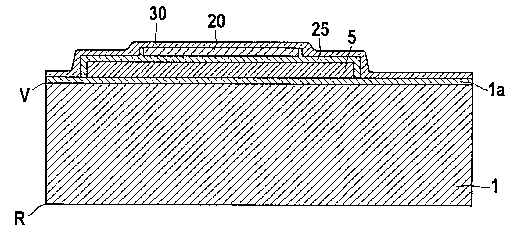
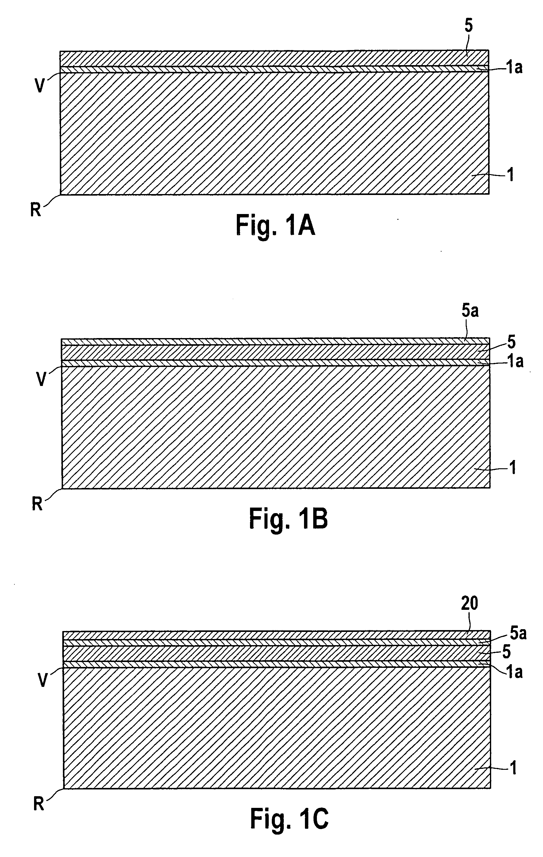
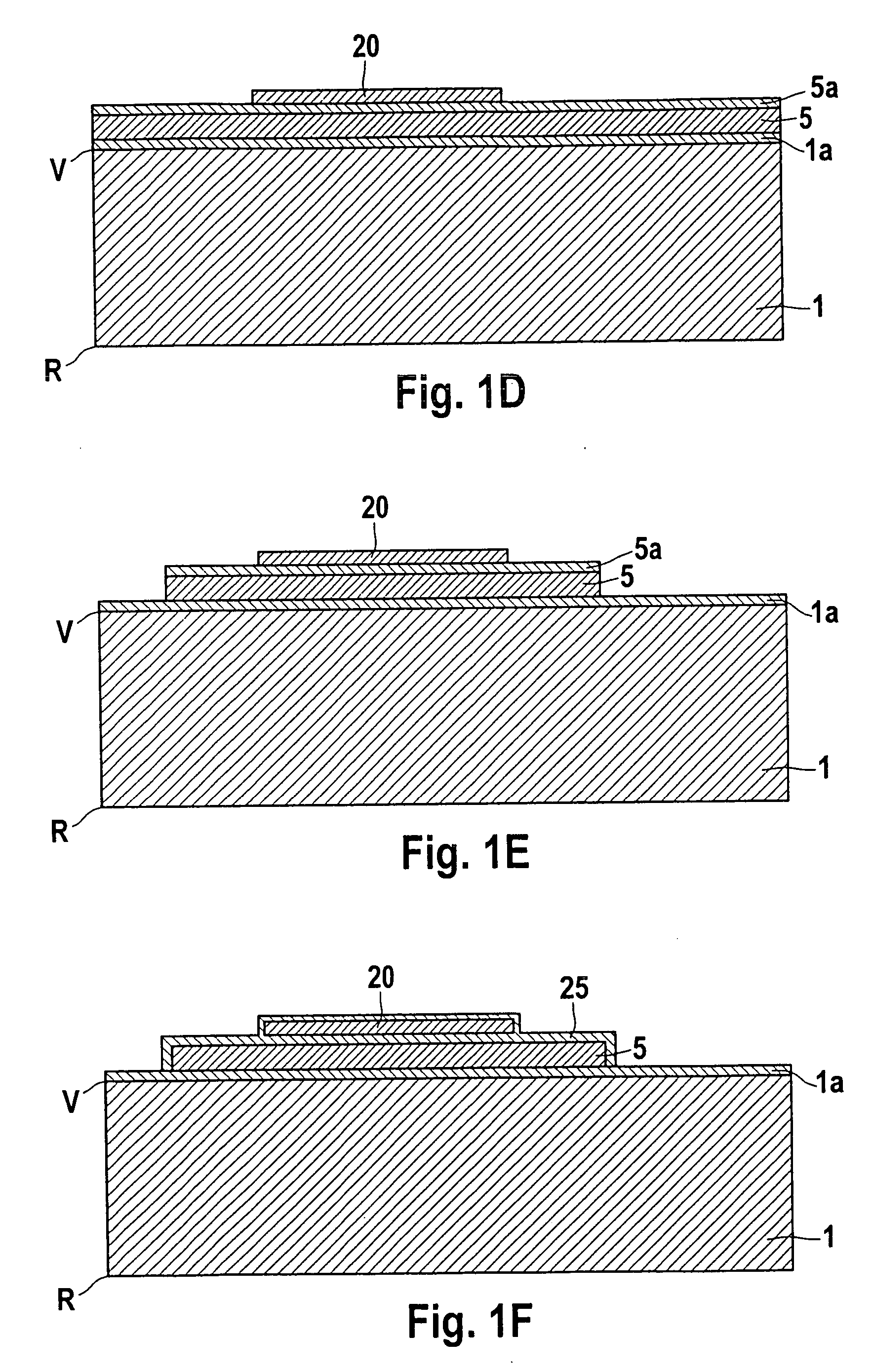
[0019] FIGS. 1A-L show schematic cross-sectional views of the essential manufacturing steps of a micromechanical component in the form of a capacitive pressure sensor, according to a first specific embodiment of the present invention.

[0020] The idea forming the basis of the first specific embodiment is to overcome the effect of curved diaphragm parts on the measured capacitance and, therefore, to overcome the nonlinearity of the sensor elements, by reducing or completely suppressing the curvature of the diaphragm electrode in the region where measured capacitance is generated, i.e. where the measured signal is generated in conjunction with a lower counterelectrode.

[0021] In the first specific embodiment, an inner part of the diaphragm is stiffened by building it up, so that the curvature is reduced for a large part of the surface that contributes to the generation of the measured signal. However, the outer parts of the diaphragm (the edge region) are not built up, which means that...


PUM


Abstract

A micromechanical component having a substrate conductive in at least some regions; an elastically deflectable diaphragm, which is conductive in at least some regions, arches over a front side of the substrate, and is electrically insulated from the substrate, the diaphragm having an inner region (I; I′) and an edge region (RB; RB′); and a hollow space (H), which is provided between the substrate (1) and the diaphragm (M); the inner region (I; I′) having a cross-section that is modified in comparison with the edge region (RB; RB′), which means that the bending of the inner region (I; I′) is less than that in the case of an identical cross-section.

Description

FIELD OF THE INVENTION [0001] The invention relates to a micromechanical component and to a corresponding manufacturing method. DESCRIPTION OF RELATED ART [0002] Although applicable, in principle, to a multitude of micromechanical components, the present invention, as well as the problem forming the basis of it, are explained on the basis of capacitive pressure sensors. [0003] The starting point for explaining the underlying problem is a capacitive pressure sensor, e.g. a relative pressure sensor, in which the capacitance of an upper diaphragm with respect to a counterplate formed by the substrate or in another manner, e.g. in the form of a lower polysilicon electrode, is evaluated in the form of a pair of electrodes. The deflection of the center of a diaphragm fixed on all sides is known to be linearly proportional to the applied pressure or the pressure difference over a wide range. The capacitance of the capacitor formed by the diaphragm and counterelectrode is a reciprocal funct...

Claims


Application Information

Patent Timeline
Patent Type & Authority Applications(United States)
IPC IPC(8): H01L21/00H01L29/82
CPCB81B3/0086B81B2201/0264G01L9/0073G01L9/0042B81B2203/0109
Inventor LARMER, FRANZKRONMULLER, SILVIALEINENBACH, CHRISTINA
Owner ROBERT BOSCH GMBH
Learn More