
Flexible OLED display panel bending area wiring structure and flexible OLED display panel

A display panel and line structure technology, applied in the direction of electrical components, electric solid devices, circuits, etc., can solve the problems affecting the stability of the SD connection of the wiring change layer, corrosion, and affecting the characteristics of the device

Active Publication Date: 2018-05-29
WUHAN CHINA STAR OPTOELECTRONICS SEMICON DISPLAY TECH CO LTD
View PDF7 Cites 24 Cited by
  • Summary
  • Abstract
  • Description
  • Claims
  • Application Information

AI Technical Summary

Benefits of technology

This new type of flat-screen technology solves problems with traditional methods used by electronic devices such as cathode ray tubes (CRTs). It does this because it doesn't require any layers on top or under that are needed when bent around corners instead of just being connected through external connections like signal lines between different parts inside an electronics device itself.

Problems solved by technology

This patented describes a technical problem related to improving flexibility in electronic displays by reducing stresses caused from external factors like impact or pressure that may occur over the bent areas where different layers are joined together.

Method used


Image

  • Flexible OLED display panel bending area wiring structure and flexible OLED display panel
  • Flexible OLED display panel bending area wiring structure and flexible OLED display panel
  • Flexible OLED display panel bending area wiring structure and flexible OLED display panel

Examples


Embodiment Construction

[0027] Hereinafter, embodiments of the present invention will be described in detail with reference to the accompanying drawings. This invention may, however, be embodied in many different forms and should not be construed as limited to the specific embodiments set forth herein. Rather, the embodiments are provided to explain the principles of the invention and its practical application, thereby enabling others skilled in the art to understand the invention for various embodiments and with various modifications as are suited to particular intended uses.

[0028] In the drawings, the thicknesses of layers and regions are exaggerated for clarity. Like reference numerals refer to like components throughout the specification and drawings.

[0029] It will be understood that, although the terms "first", "second", etc. may be used herein to describe various elements, these elements should not be limited by these terms. These terms are only used to distinguish one element from anot...


PUM


Abstract

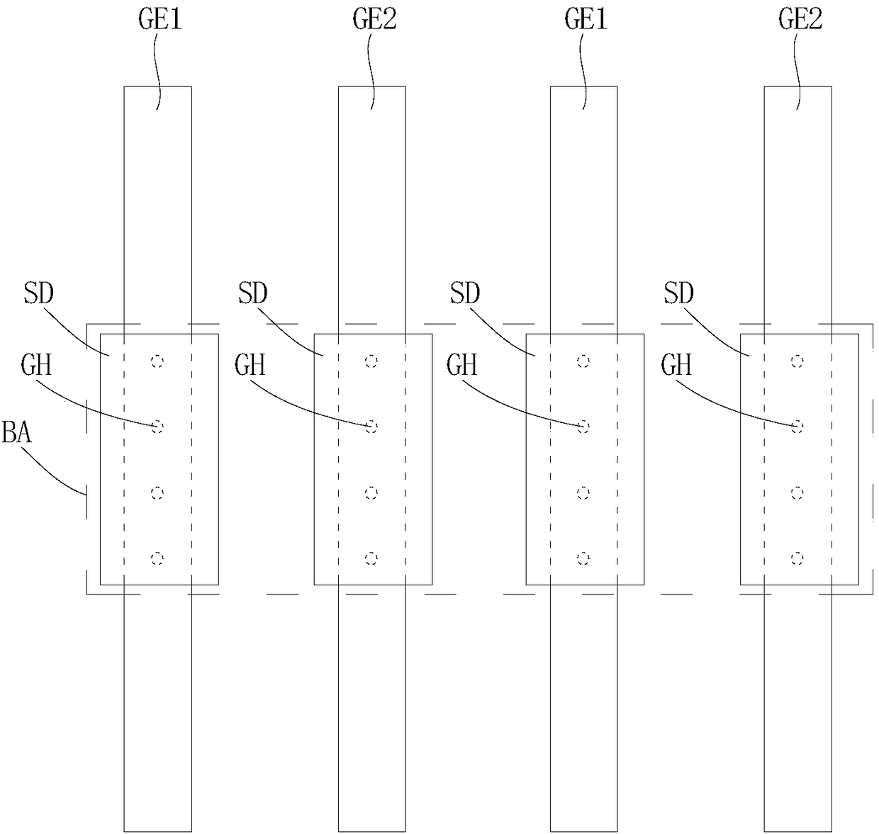
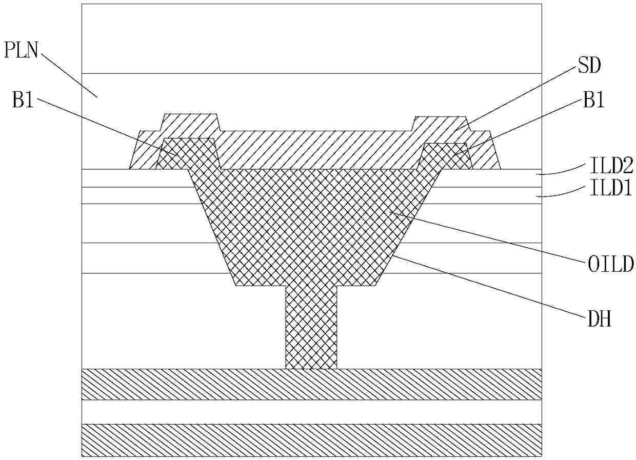
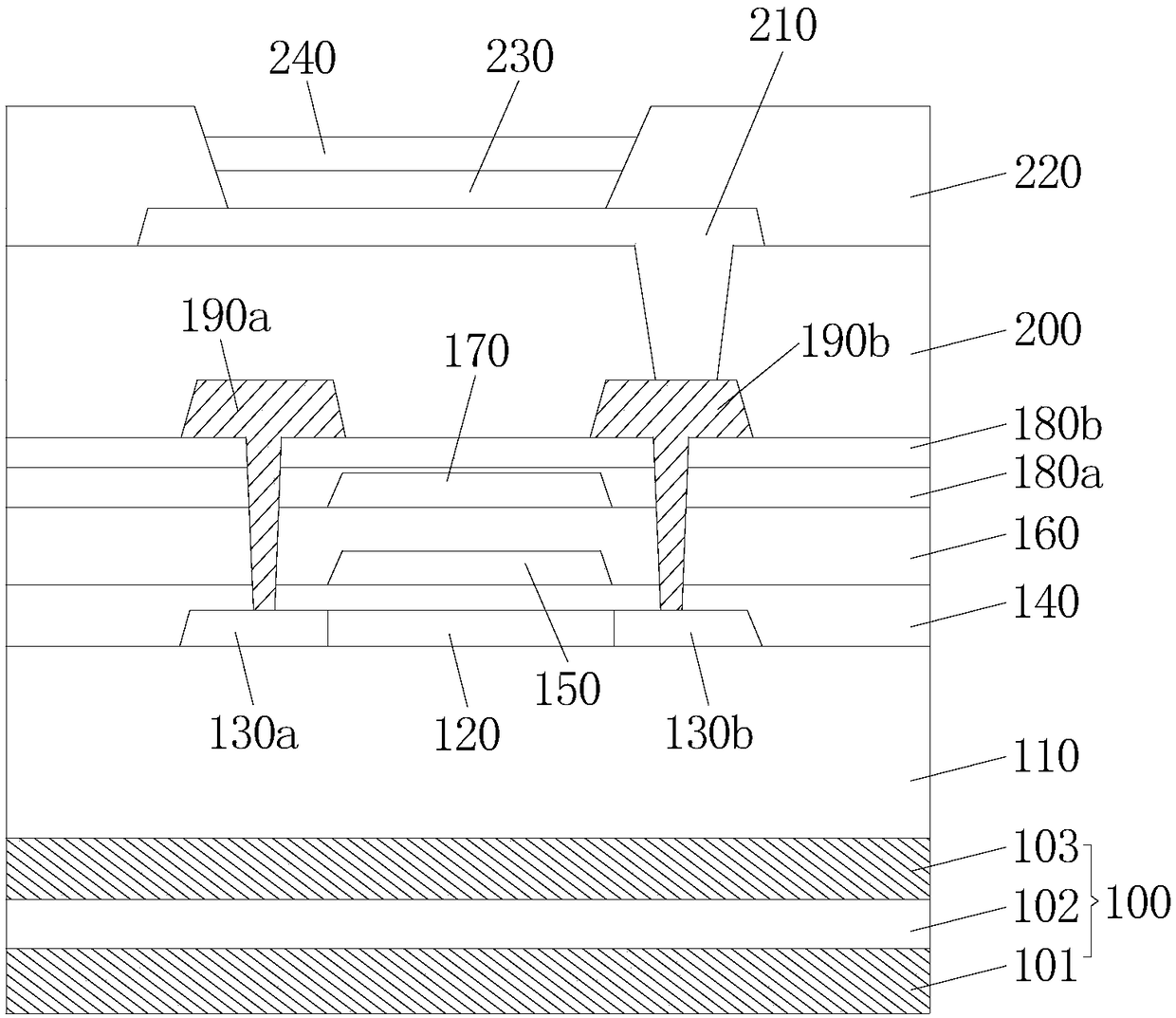
The invention provides a flexible OLED display panel bending area wiring structure. The wiring structure comprises a number of first conductive strips, an insulating layer and a number of second conductive strips. A number of first conductive strips are spaced apart. The insulating layer is arranged on a number of first conductive strips and in the spacing between the first conductive strips. A number of second conductive strips are arranged on the insulating layer with spacing. A number of second conductive strips run through the insulating layer and are connected with a number of first conductive strips. According to the invention, the existing wiring line replacement layer in a flexible OLED display panel bending area is omitted; the wiring structure of the bending area still has the characteristic of effective stress release when the wiring structure is bent; and the risk of bending and breakage is avoided.

Description


Claims


Application Information

Patent Timeline
Owner WUHAN CHINA STAR OPTOELECTRONICS SEMICON DISPLAY TECH CO LTD
Learn More