Furnace tube device

A furnace tube and ventilation tube technology, applied in the field of semiconductor manufacturing equipment, can solve the problems of long distribution span of wafers and differences in wafer processing effects, etc., and achieve the effect of improving product yield

Active Publication Date: 2018-05-29
上海昭帆智能科技有限公司
View PDF5 Cites 3 Cited by
  • Summary
  • Abstract
  • Description
  • Claims
  • Application Information

AI Technical Summary

Problems solved by technology

[0006] The problem solved by the present invention is that the wafers in the existing furnace tube device can only be arranged sequentially along the height direction of the furnace tube device, so that the distribution span of the wafers is long, resulting in a large difference in the wafer processing effect

Method used


Image

  • Furnace tube device
  • Furnace tube device
  • Furnace tube device

Examples


Embodiment Construction

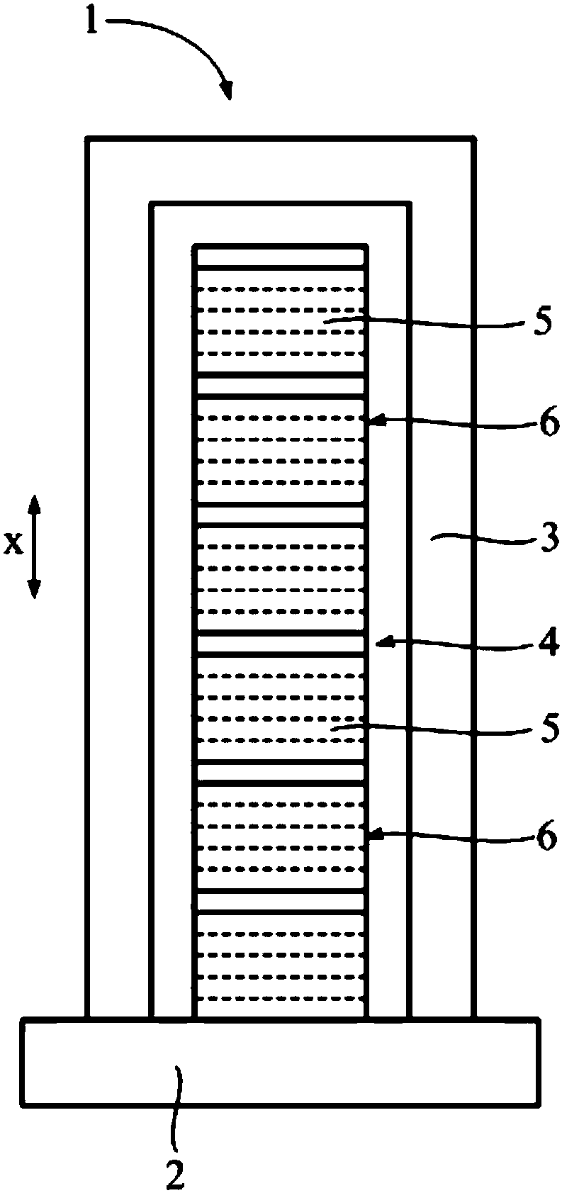
[0023] refer to figure 1 , the furnace tube device 1 in the prior art has a larger height, so that the furnace tube cavity 4 has a longer distance along the height direction x, so that more wafers 5 can be stacked in the height direction, so as to simultaneously Multiple wafers 5 are oxidized, doped or heat-treated.

[0024] In the process of using the furnace tube device 1 to process the wafer 5, for example, when a silicon nitride (SiN) film needs to be deposited on the surface of the wafer 5, dichlorosilane (DCS) and ammonia (NH 3 ) and other process gases are passed into the furnace cavity 4; at the same time, the furnace cavity 4 needs to be heated to heat the wafer 5, and dichlorosilane and ammonia react on the surface of the wafer 5 to form a silicon nitride film.

[0025] However, since the furnace tube cavity 4 has a long distance along the height direction x, the distribution of dichlorosilane and ammonia in the furnace tube cavity 4 will be uneven, and dichlorosila...


PUM


Abstract

A furnace tube device comprises a base and a shell, a furnace tube cavity for containing wafers is defined by the base and the shell, multiple trays used for containing the wafers is formed in the surface, facing the furnace tube cavity, of the base. The multiple trays are arranged on the base, the wafers can be placed on the trays in a dispersed manner, and therefore the height of the furnace tube cavity can be reduced. When the height of the furnace tube cavity is reduced, it means that the distance between the wafers at the two ends in the height direction is reduced, the process conditionsof the wafers are close, each wafer has the quite close treatment effect, and the product yield is improved.

Description

technical field [0001] The invention relates to the technical field of semiconductor manufacturing equipment, in particular to a furnace tube device. Background technique [0002] The furnace tube device is the basic equipment in the semiconductor manufacturing process, which is mainly used for the oxidation, doping and heat treatment of the wafer. During use, the wafer is placed inside the furnace tube device, the furnace tube device is heated, and the process gas is passed into the furnace tube device to realize the oxidation, doping and heat treatment of the wafer. [0003] refer to figure 1 , the furnace tube device 1 in the prior art includes a base 2 and a shell 3, the base 2 and the shell 3 enclose a furnace tube cavity 4, and a wafer 5 is arranged in the furnace tube cavity 4. Wherein, the casing 3 is provided with a ventilation pipe (not shown in the figure), which is suitable for passing process gas into the furnace tube cavity 4, and the furnace tube device 1 al...

Claims


Application Information

Patent Timeline
Patent Type & Authority Applications(China)
IPC IPC(8): F27B17/00F27D1/00F27D5/00
CPCF27B17/0025F27D1/0043F27D5/0037
Inventor 邸太平洪纪伦倪明明吴宗祐林宗贤
Owner 上海昭帆智能科技有限公司
Why Eureka
Try Eureka