
Transmission device for capping machine

A technology of conveying device and capping machine, which is used in conveyor control device, transportation and packaging, conveyor and other directions, can solve problems such as bottle dumping, potential safety hazards for equipment and operators, and non-compliance with electrical safety regulations when pulling gates with load. , to achieve the effect of convenient shutdown

Inactive Publication Date: 2018-05-29
沈阳星辉利包装机械有限公司
View PDF0 Cites 0 Cited by
  • Summary
  • Abstract
  • Description
  • Claims
  • Application Information

AI Technical Summary

Problems solved by technology

[0003] The transmission device of the existing capping machine usually has only one conveyor, and since such equipment has no guardrails on the front, rear, left, and right sides, it is easy to cause the bottle to fall in practical applications. Install the guardrail, but after installing the guardrail, since the guardrail touches the bottle, there will be friction between the two, and the bottle body will be easily scratched, so people would rather not have the guardrail. How to solve these problems is the problem we are facing now
In order to meet the process and production requirements, in some special cases when transporting bottles, the operator should immediately cut off the material and stop the operation of the equipment. However, if the operator cannot or does not arrive in time and cannot stop the machine, accidents of bottle accumulation will occur.
If the pump of the outage machine is a high-power motor, it is very risky to switch on the load and does not meet the electrical safety regulations, which poses a huge safety hazard to equipment and operators

Method used


Image

  • Transmission device for capping machine
  • Transmission device for capping machine

Examples


Embodiment Construction

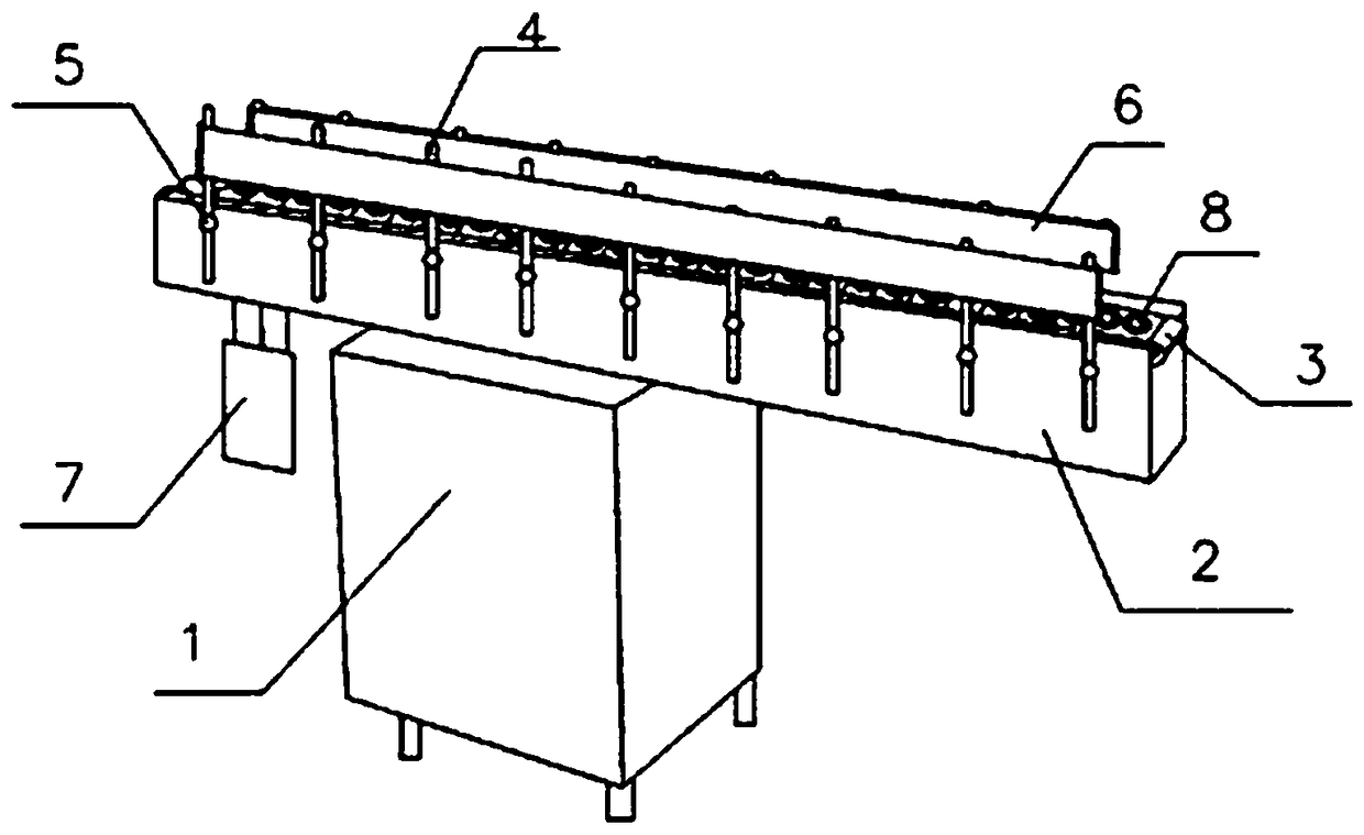
[0014] according to Figure 1~2 The specific structure of the present invention will be described in detail. The transmission device used by this capping machine includes a support 1, a conveyor 2, a positioning conveyor belt 3, and a guide bar 4, wherein the conveyor 2 is fixed on the support 1, and the guide bar 4 is located on both sides of the conveyor 2, and the positioning conveyor belt 3 is spaced apart. There is a positioning groove 8, and the entire positioning conveyor belt 3 is made of plastic, which is directly set on the conveyor belt of the conveyor 2, which is convenient for disassembly. The conveyor 2 is driven by the driver 7, and the size of the positioning groove 8 can be adjusted according to the size of the bottom of the bottle. Formulate; the both sides of conveyor 2 are provided with fixed rods 5 at intervals, and guide bar 4 is fixed on the fixed rods 5 on both sides of conveyor 1 by bolts, and the position can be adjusted forward and backward according...


PUM


Abstract

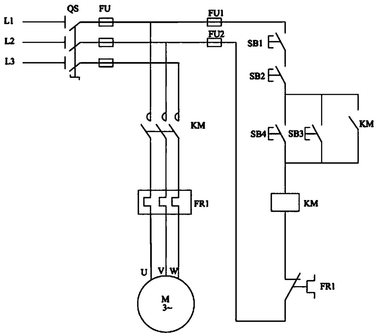
The invention provides a transmission device for a capping machine and solves the problems that bottle bodies are easily scratched due to the friction of guardrails and bottles after the guardrails are in contact with the bottles and emergent stop causes bottle stacking accidents in the prior art. The transmission device comprises a bracket, a conveyer, a locating conveyer belt and guide rails, wherein the conveyer is fixedly arranged on the bracket, the guide rails are arranged at the two sides of the conveyer, locating grooves are arranged on the locating conveyer belt at intervals, and thewhole locating conveyer belt is arranged on a conveyer belt of the conveyer in a sleeving manner; fixing rods are arranged at the two sides of the conveyer at intervals, and the guide rails are fixedly arranged on the fixing rods at the two sides of the conveyer through bolts; rollers are arranged on the guide rails, and the conveyer belt is arranged on the rollers; and a button SB2 and a button SB4 are arranged in a control loop of a low-voltage motor control circuit, and a button SB5 is arranged in a stop loop of a high-voltage motor control circuit. The transmission device is reasonable indesign, compact in structure and reasonable in space occupation, prevents the bottle bodies from being scratched and carries out stable transmission and convenient, rapid, safe and reliable stop.

Description

technical field [0001] The invention belongs to the technical field of packaging machinery, and in particular relates to a transmission device for a cap locking machine that can avoid friction, prevent bottle body scratches, and transmit smoothly. Background technique [0002] Capping machine, its function is to lock the bottle cap of the bottle filled with the substance. Locking the bottle cap requires a certain amount of torque. Bottles of different sizes, shapes, and materials require different torques to lock the cap. [0003] The transmission device of the existing capping machine usually has only one conveyor, and since such equipment has no guardrails on the front, rear, left, and right sides, it is easy to cause the bottle to fall in practical applications. Install the guardrail, but after installing the guardrail, because the guardrail touches the bottle, there will be friction between the two, and the bottle body will be easily scratched, so people would rather no...

Claims


Application Information

Patent Timeline
Patent Type & Authority Applications(China)
IPC IPC(8): B65G15/58B65G21/20B65G43/00
CPCB65G15/58B65G21/20B65G43/00
Inventor 许森林
Owner 沈阳星辉利包装机械有限公司
Learn More