
Air inflation and exhaust blade structure of wind-driven generator

A wind turbine and blade structure technology, which is applied to wind turbine components, wind engines, and wind turbines in the same direction as the wind, and can solve the problems of high manufacturing, transportation and installation costs, complex large blade structures, and high equipment maintenance costs , so as to achieve the effects of small unit structural stress, low manufacturing and maintenance costs, and reduced blade weight

Inactive Publication Date: 2013-05-22
TSINGHUA UNIV
View PDF5 Cites 0 Cited by
  • Summary
  • Abstract
  • Description
  • Claims
  • Application Information

AI Technical Summary

Problems solved by technology

[0013] The purpose of the present invention is to provide a blade structure of an air-inflating type wind power generator to solve the disadvantages of large-scale blades in the prior art, such as complex structure, high manufacturing, transportation and installation costs, high equipment maintenance costs, and large safety risks. It has the characteristics of light weight, low manufacturing and maintenance costs, and controllable wind and force states, so as to meet the requirements of large wind turbines for blade structure

Method used


Image

  • Air inflation and exhaust blade structure of wind-driven generator
  • Air inflation and exhaust blade structure of wind-driven generator

Examples


Embodiment Construction

[0022] Below in conjunction with accompanying drawing, structure of the present invention and specific embodiment are described further:

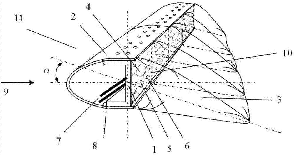
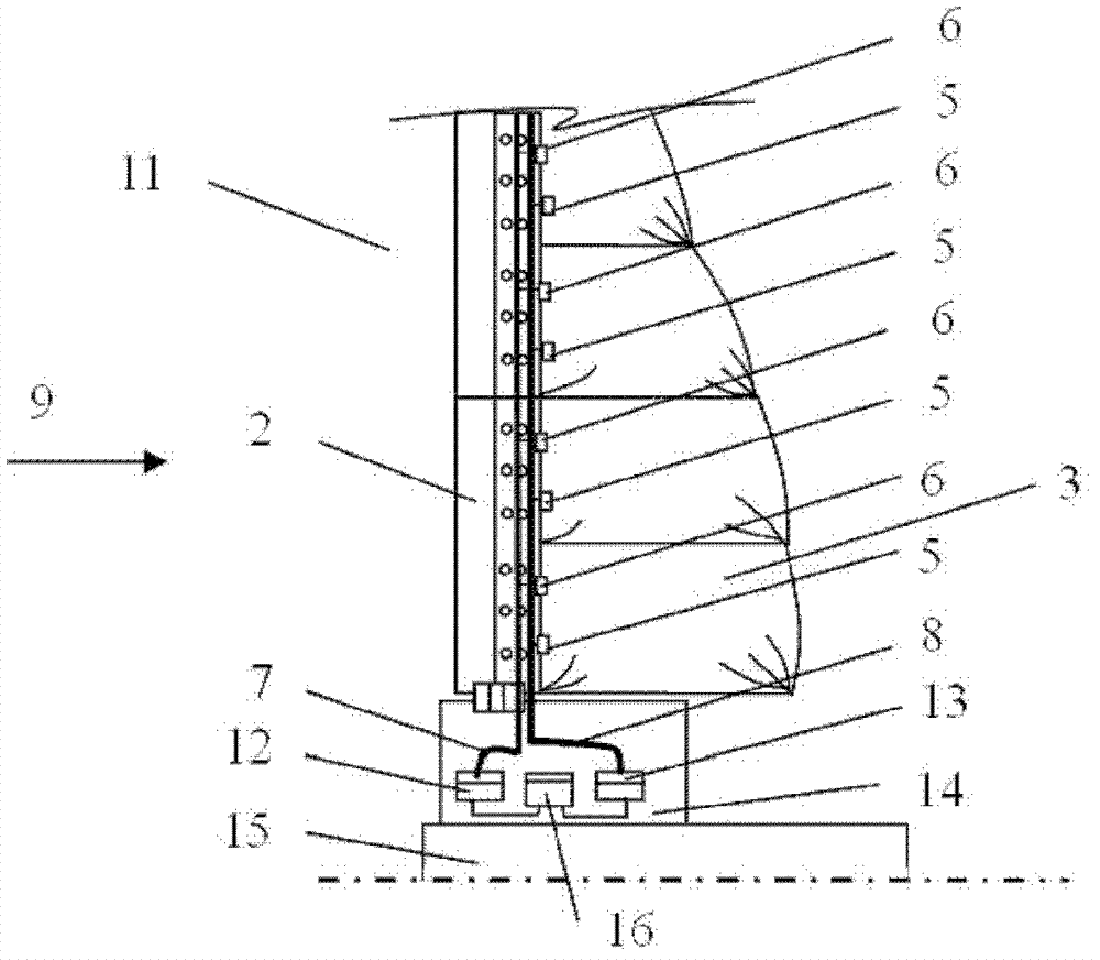
[0023] figure 1 It is a schematic diagram of the blade structure of the air charging and pumping type wind power generator provided by the present invention. The blade includes a skeleton beam 1, a front wing panel 2 and a rear wing airbag 3; the skeleton beam adopts a constant cross-section along the length direction of the blade, or adopts a gradually smaller variable cross-section, which is stronger on the side near the blade root, and closer to the blade root. The tip side of the blade is weaker. The rear wing airbag 3 adopts an integral airbag, and can also be composed of individual segmented airbags. The use of each independent segmented airbag can better control the stress state of the blade; generally, large blades use independent Segmented airbags are combined, while small and medium blades are in the form of integral airbags; th...


PUM


Abstract

An inflatable / deflatable wind turbine blade structure comprising a blade (11), a wind turbine wheel (14), and a wind turbine main shaft (15). The blade (11) and the wind turbine wheel housing (14) are connected, while the wind turbine wheel housing (14) is arranged on the wind turbine main shaft (15). The blade (11) comprises a frame beam (1), a front wing panel (2), and a rear wing airbag (3). The frame beam (1) is provided with a channel section, constituted by a vertical side plate (10) and upper and lower side plates. The frame beam (1) employs a constant section along a lengthwise direction of the blade (11), or employs a variable section gradually decreasing in size. The rear wing airbag (3) and the vertical side plate (10) are connected via a bolt. The rear wing airbag (3) is provided thereon with an inflation valve (4) and a deflation valve (8). The front wing panel (2) is fixed to the upper and lower side plates of the frame beam (1). Consisting of the frame beam (1), the front wing panel (2), and the rear wing panel (3), the cross section of the blade (11) is provided with an aerodynamically streamlined shape and structure. The structure has the advantages of reduced manufacturing and maintenance costs, and of improved safety.

Description

technical field [0001] The invention relates to a blade structure of a wind power generator, in particular to a blade structure of an air charging and pumping type wind power generator, and belongs to the technical field of wind power generation equipment. Background technique [0002] Most of today's energy sources are fossil fuels: coal, oil, and natural gas. At current rates of use, the remaining known coal deposits will be used up in about 200 years, while oil and gas will be used up in less than 100 years. do. Fossil fuels cause a lot of environmental pollution when used, including greenhouse gases that contribute to global warming. Wind energy is one of the most commercially viable and dynamic renewable energy sources. It is clean, low-cost, and inexhaustible. Wind power has the advantages of large growth space for installed capacity, rapid cost reduction, safety, and energy never being exhausted. Wind power can effectively alleviate air pollution, water pollution a...

Claims


Application Information

Patent Timeline
Patent Type & Authority Patents(China)
IPC IPC(8): F03D11/00
CPCF03D1/0675Y02E10/722F05B2240/31F05B2240/311F03D11/00Y02E10/721F03D1/00F05B2240/312F03D80/00Y02E10/72Y02P70/50
Inventor 曾攀
Owner TSINGHUA UNIV
Learn More