
Pin removal device for semi-trailer tractor and use method of device

A tractor and tractor pin technology, applied in traction connectors, vehicle parts, transportation and packaging, etc., can solve the problem of not being suitable for semi-trailer tractors

Pending Publication Date: 2018-05-22
DONGFENG COMML VEHICLE CO LTD
View PDF11 Cites 0 Cited by
  • Summary
  • Abstract
  • Description
  • Claims
  • Application Information

AI Technical Summary

Problems solved by technology

[0004] The purpose of the present invention is to overcome the problem that the prior art is not suitable for semi-trailer tractors, and provide a semi-trailer depinning device and its use method

Method used


Image

  • Pin removal device for semi-trailer tractor and use method of device

Examples


Embodiment 1

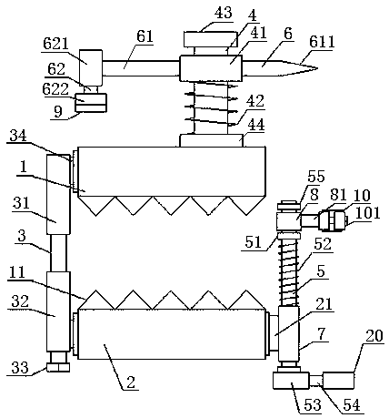
[0047] see figure 1 , a pin-out device for a semi-trailer tractor, including a car state clamping upper part 1 and a car state clamping lower part 2 with the same structure, a telescopic fixed rod 3, a No. 1 sliding rod 4, a No. 2 sliding rod 5, and a No. 1 screw rod 6. No. 1 sliding cylinder 7, the bottom surface of the clamping upper part 1 of the car state, and the top surface of the lower part 2 of the clamping state of the car state are provided with sawtooth 11, and the telescopic fixing rod 3 includes an upper fixing cylinder 31, a lower fixing cylinder 32. No. 2 screw 33, the No. 2 screw 33 passes through the lower fixing barrel 32 and is threadedly connected with the inner wall of the upper fixing barrel 31, and the side walls of the upper fixing barrel 31 and the lower fixing barrel 32 pass through the No. 1 connecting rod 34 are respectively welded with one end of the clamping upper part 1 of the car state and the lower part 2 of the clamping state of the car state,...

Embodiment 2

[0052] Structure is the same as embodiment 1, and difference is:

[0053] In the second step, the top of the traction pin is a plane structure, the user first slides down and rotates the sleeve 41 horizontally, so that the magnet 9 is attracted to the top of the traction pin to fix the top of the traction pin, and then steps on the pedal 20. Make the snap ring 10 collide with the positioning screw located at the tip of the traction pin until the positioning screw changes from a horizontal state to a vertical state. At this time, the No. 1 coil spring 42 pushes the sleeve 41 to slide upward under the action of its elastic force, vertically The rod 621 drives the traction pin to move upwards to realize depinning.


PUM


Abstract

A pin removal device for a semi-trailer tractor comprises a tractor side clamping upper part, a tractor side clamping lower part, a clamping ring, a stepping block, a transverse rod or a magnet, a first spiral spring and a sleeve, wherein the tractor side clamping upper part and the tractor side clamping lower part are used for fixing the pin removal device; the clamping ring is in sealed fit withthe bottom of a traction pin; the stepping block drives the clamping ring to collide with a positioning screw of the traction pin to release positioning; the transverse rod or the magnet is used forfixing the top of the traction pin; the first spring and the sleeve drive the traction pin to move upwards to achieve pin removal. When the device is used, the tractor side clamping upper part and thetractor side clamping lower part are used for clamping the tractor side, then the clamping ring is in sealed fit with the bottom of the traction pin, then the top of the traction pin is fixed, the stepping block is treaded, so that the clamping ring collides with the positioning screw at the tip of the traction pin till positioning is released, finally, the first spiral spring pushes the sleeve to slide upwards under the action of elastic force of the first spiral spring, and the traction pin is driven to move upwards to achieve pin removal. By means of the design, removal of traction pins, different in structure, of the semi-trailer tractor can be achieved.

Description

technical field [0001] The invention belongs to the field of automobile processing, and in particular relates to a depinning device for semi-trailer tractors and a use method thereof, which is suitable for depinning of traction pins of different structures of semi-trailer tractors. Background technique [0002] The headstock of tractor can break away from original carriage and tow other carriages, and carriage also can break away from original carriage and be pulled by other carriages, so tool traction is needed between its headstock and carriage. General large-scale trucks usually use pins to fix the front and carriage for traction, and the existing pins are generally divided into workpieces with a round top and a cylinder connected to the bottom and a flat top with a cylinder connected to the bottom. Users prepare tools such as wrenches and screwdrivers, which is not only cumbersome and time-consuming, but also inconvenient to fix, which affects work efficiency. [0003] ...

Claims


Application Information

Patent Timeline
IPC IPC(8): B60D1/24B60D1/58
CPCB60D1/24B60D1/58
Inventor 徐团张明凯方红高鑫
Owner DONGFENG COMML VEHICLE CO LTD
Learn More