
Anti-wall-adhering reaction kettle

A technology of reaction kettle and anti-stick wall, which is applied in chemical/physical/physical-chemical stationary reactors, mixers with rotary stirring devices, mixers, etc. Obvious and other problems, to achieve the effect of enhancing the de-sticking effect

Active Publication Date: 2017-05-17
重庆依尔双丰科技有限公司
View PDF5 Cites 16 Cited by
  • Summary
  • Abstract
  • Description
  • Claims
  • Application Information

AI Technical Summary

Problems solved by technology

The agitator is an important part in the reactor. The existing agitator uses a ring-shaped conduit to cover the rotor and stator for agitation. When working, the material rotates around the axis, and the material stuck to the inner wall of the kettle is blown by a Y-shaped air jet pipe. The stirring range of such agitator is small, and the effect of blowing off the material stuck on the wall is not obvious

Method used


Image

  • Anti-wall-adhering reaction kettle
  • Anti-wall-adhering reaction kettle
  • Anti-wall-adhering reaction kettle

Examples


Embodiment 1

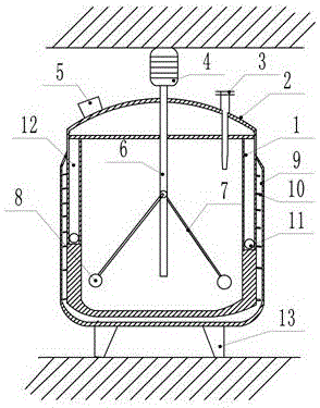
[0021] Embodiment 1 is basically as attached figure 1 And attached image 3 Shown: a reaction kettle with an anti-sticking wall, which is mainly composed of a kettle body 1, a support 13, a stirring unit and a transmission 4. The kettle body 1 is a non-ferrous material, and the non-ferromagnetic material is a material that cannot attract each other with a magnet. The kettle body 1 is composed of a cylinder and a lower head. The outer wall of the cylinder is coiled with slats 10. The barrel and the lower head are surrounded by a U-shaped jacket 9. Both sides of the kettle body 1 are provided with compartments 12, and movable blocks 11 that can be attracted by magnetic substances are placed in the compartments 12. A kettle cover 2 is installed on the upper end of the kettle body 1, and the left end of the kettle cover 2 is provided with a feed port 5, and the right end of the kettle cover 2 is fixed with a thermometer sleeve 3, and the thermometer sleeve 3 runs through the ket...

Embodiment 2

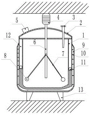
[0024] Embodiment 2 is basically as attached figure 2 Shown:

[0025] The difference between this embodiment and Embodiment 1 is that the inner wall of the kettle body 1 is arranged obliquely and is in the shape of a funnel. When the spherical magnet is attracted by the magnetic force, the spherical magnet is more likely to overcome gravity under the action of the magnetic force and the supporting force, so that it can be faster. It moves more easily and bumps into the inner wall of the compartment to enhance the vibration effect; the inner wall of the compartment 12 is coated with anti-impact material to prevent the spherical magnet from causing damage to the inner wall of the kettle body 1; the movable block 11 that can be attracted by the magnetic material is a spherical magnet. When the spherical magnet hits the inner wall of the compartment 12 due to the magnetic force, the stressed surface of the compartment 12 is smaller and the pressure is greater, and the vibration o...


PUM

PropertyMeasurementUnit
Thicknessaaaaaaaaaa

Abstract

The invention belongs to the field of chemical equipment, and particularly discloses an anti-wall-adhering reaction kettle. The anti-wall-adhering reaction kettle comprises a kettle body, wherein the inner wall of the kettle body is made from a non-ferromagnetic material, and provided with an isolated cavity; a movable block which can be attracted by a magnetic substance is arranged in the isolated cavity; the top end of the kettle cover is provided with a driver which is fixed to the machine frame; the driver is rotatablely connected with a stirring unit positioned in the kettle body; the stirring unit comprises a stirring shaft; a plurality of stirring rods are hinged on the stirring shaft; and the working end of each stirring rod is fixedly provided with a stirring magnetic block. The anti-wall-adhering reaction kettle has the advantages of simple structure, uniform stirring and obvious anti-adhering effect.

Description

technical field [0001] The invention belongs to the field of chemical equipment. Background technique [0002] Reactor is one of the essential equipment in the production of chemical industry. As we all know, there are many kinds of reactors, which are widely used in petroleum, chemical industry, food, medicine, pesticide, scientific research and other industries. They are used to complete polymerization, condensation, vulcanization, Reaction equipment for chemical processes such as alkylation and hydrogenation. The agitator is an important part in the reactor. The existing agitator uses a ring-shaped conduit to cover the rotor and stator for agitation. When working, the material rotates around the axis, and the material stuck to the inner wall of the kettle is blown by a Y-shaped air jet pipe. The mixing range of such agitator is small, and the effect of blowing off the materials stuck on the wall is not obvious. Contents of the invention [0003] The object of the pres...

Claims


Application Information

Patent Timeline
IPC IPC(8): B01J19/02B01J19/18B01F7/18
CPCB01J19/0066B01J19/02B01J19/18B01J2219/0213B01J2219/00063B01F27/0531B01F27/054B01F27/90B01F35/145B01F2101/2204
Inventor 赵家永
Owner 重庆依尔双丰科技有限公司
Learn More