
Method for eliminating visual error between forward-looking infrared device and head-up display

A head-up display and forward-looking infrared technology, applied in the field of aviation optoelectronics, can solve problems such as visual errors, and achieve the effect of solving visual errors and eliminating visual errors

Active Publication Date: 2018-05-18
LUOYANG INST OF ELECTRO OPTICAL EQUIP OF AVIC
View PDF3 Cites 2 Cited by
  • Summary
  • Abstract
  • Description
  • Claims
  • Application Information

AI Technical Summary

Problems solved by technology

[0004] In order to avoid the deficiencies of the prior art, the present invention proposes a method for eliminating the visual error between the forward-looking infrared device and the head-up display, and solves the problem of the visual error caused by the distance deviation between the forward-looking infrared device and the head-up display due to the installation position on the machine. question

Method used


Image

  • Method for eliminating visual error between forward-looking infrared device and head-up display
  • Method for eliminating visual error between forward-looking infrared device and head-up display
  • Method for eliminating visual error between forward-looking infrared device and head-up display

Examples


Embodiment Construction

[0028] Now in conjunction with embodiment, accompanying drawing, the present invention will be further described:

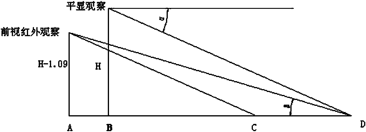
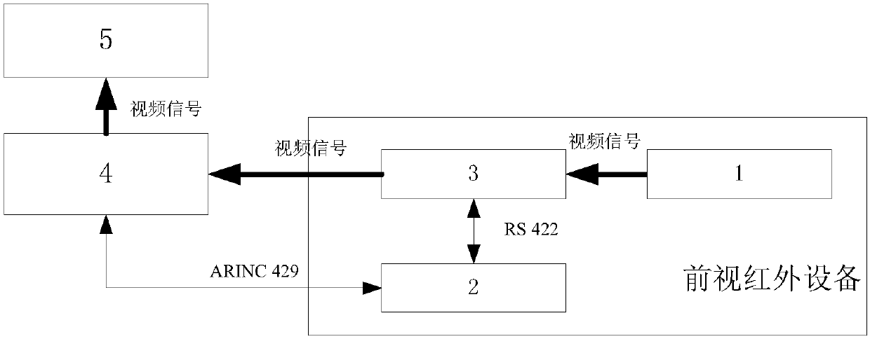
[0029] see image 3 , where 1, 2, and 3 constitute the forward-looking infrared device, the boresight error calculation runs in 2, and the image translation and shearing runs in 3.

[0030] After the forward-looking infrared device is installed on the aircraft, its installation position on the aircraft is relative to the head-up display, and the pitch angle of the visual axis relative to the body coordinate system is a definite value, which is a definite value. The coordinates of the forward-looking infrared device can be obtained as Rb=[ Rx; Ry; Rz], pitch angle α. By calibrating the target on the aircraft, it can ensure that the visual axis of the forward-looking infrared equipment is parallel to the visual axis of the head-up display.

[0031] Through the ARINC 429 bus 2, the flight altitude, aircraft pitch angle, and aircraft roll angle are received from 4,...


PUM


Abstract

The invention relates to a method for eliminating a visual error between a forward-looking infrared device and a head-up display. By calculating a deviation of a visual axis of the forward-looking infrared device relative to a visual axis of the head-up display according to attitude data of a carrier aircraft, performing translation and shear processing on an infrared image output by the forward-looking infrared device and sending a processed infrared image to the head-up display to display, the visual error caused by mounting positions of the forward-looking infrared device and the head-up display can be solved, and an image displayed by the forward-looking infrared device on the head-up display is guaranteed to be consistent with an outside scene image seen by a driver via the head-up display.

Description

technical field [0001] The invention belongs to the technical field of aviation optoelectronics, and relates to a method for eliminating visual errors between forward-looking infrared equipment and heads-up displays Background technique [0002] The forward-looking infrared device detects and images the front of the aircraft route, and superimposes the detected image on the head-up display directly in front of the driver's line of sight for the driver to observe. There is inevitably a distance deviation between the forward-looking infrared device and the head-up display on the aircraft. When the aircraft lands very close to the runway or taxis on the airport ground, this installation position difference will cause visual errors, which will be superimposed on the head-up display at night. The image screen of the forward-looking infrared device on the vehicle is inconsistent with the external scene image viewed by the driver through the head-up display, causing the driver to f...

Claims


Application Information

Patent Timeline
Patent Type & Authority Applications(China)
IPC IPC(8): H04N5/262H04N5/33H04N7/18
CPCH04N5/262H04N5/2628H04N5/33H04N7/18
Inventor 孙辉辉焦晓鹏王海潇
Owner LUOYANG INST OF ELECTRO OPTICAL EQUIP OF AVIC
Learn More