
Two-way quick hydraulic cylinder

A hydraulic cylinder, fast technology, applied in the direction of fluid pressure actuation device, etc., can solve the problems of inaccurate extension length, fast extension speed, etc., and achieve the effect of increasing the shrinkage rate, reducing the stretching speed, and accelerating the return speed

Active Publication Date: 2018-05-18
CHONGQING WEIQING HYDRAULIC MACHINERY CO LTD
View PDF8 Cites 11 Cited by
  • Summary
  • Abstract
  • Description
  • Claims
  • Application Information

AI Technical Summary

Problems solved by technology

[0006] The purpose of the present invention is to provide a two-way rapid hydraulic cylinder to solve the problem of inaccurate extension length due to the fast extension speed of the hydraulic cylinder in the final stage of extension

Method used


Image

  • Two-way quick hydraulic cylinder
  • Two-way quick hydraulic cylinder

Examples


Embodiment 1

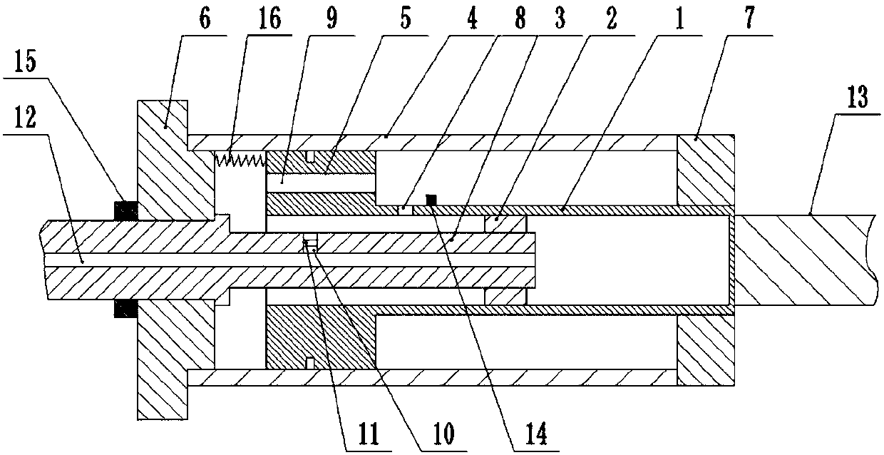
[0022] Such as figure 1 As shown, the two-way fast hydraulic cylinder includes a cylinder 1, a piston 2 and a piston rod 3 are connected inside the cylinder 1, a sealing disc 5 is connected to the left end of the cylinder 1, an oil outlet 8 is provided at the left end of the cylinder 1, and the sealing disc 5 There is an oil guide hole 9 on the top, a sleeve 4 is installed outside the sealing disc 5, the sealing disc 5 and the sleeve 4 are slidably and sealed connected, the right end of the cylinder 1 is connected with a push rod 13, the left end of the sleeve 4 is installed with a chassis 6, and the right end A fixed ring 7 is installed, the chassis 6 is fixedly connected with the piston rod 3, the piston rod 3 is provided with an oil inlet pipe 12 penetrating in the axial direction, the left end of the piston rod 3 is provided with an oil return hole 10, and a single To the valve 11, the left end of the cylinder barrel 1 is slidably and sealedly connected with the compressio...

Embodiment 2

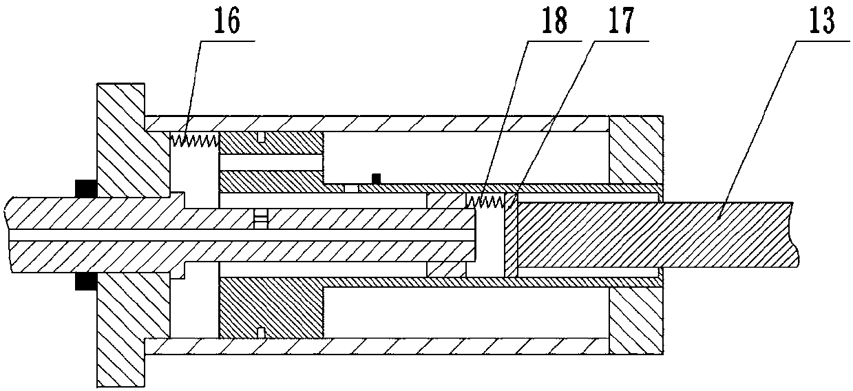
[0026] Such as figure 2 As shown, on the basis of the embodiment, a push plate 17 is installed at the left end of the push rod 13, and the push plate 17 is in sliding and sealed connection with the cylinder 1, and a second elastic member is connected between the push plate 17 and the piston 2, The second elastic part is preferably the second spring 18, which is convenient for the push rod 13 to increase the pulling force on the push plate 17 by the second spring 18 when shrinking, so as to realize rapid shrinkage; on the piston rod 3, a plurality of oil return valves evenly distributed in the axial direction are provided. A check valve 11 is installed in the hole 10 and the oil return hole 10, so as to facilitate the shrinkage of the cylinder barrel 1 and the push rod 13 to achieve a better rapid shrinkage effect.


PUM


Abstract

The invention belongs to the technical field of hydraulic equipment, and specifically discloses a two-way quick hydraulic cylinder. The two-way quick hydraulic cylinder comprises a cylinder barrel, apiston and a piston rod, wherein a sleeve is arranged at the outer side of the cylinder barrel; one end of the cylinder barrel is connected with a pushing rod; the other end of the cylinder barrel isconnected with a sealing disc; the sealing disc is in sliding and sealing connection with the sleeve; a plurality of oil conducting holes are formed in the sealing disc; one end of the sleeve is connected with a bottom disc; a plurality of first elastic pieces are connected on the bottom disc of the sealing disc; a central hole is formed in the shaft center of the bottom disc; the piston rod is fixedly connected with the bottom disc through the central hole; one end, connected with the pushing rod, of the cylinder barrel is in sliding and sealing connection with a fixed ring; the piston rod isin sliding and sealing connection with the central hole of the bottom disc; an oil outlet hole is formed in the cylinder barrel; and a through oil inlet hole is formed in the piston rod in the axialdirection. The two-way quick hydraulic cylinder is mainly used on hydraulic equipment, and solves the problem that telescopic length is inaccurate as a result of high telescopic speed at the last telescopic stage of the hydraulic cylinder.

Description

technical field [0001] The invention belongs to the technical field of hydraulic equipment, and specifically discloses a two-way rapid hydraulic cylinder. Background technique [0002] Hydraulic cylinders are often used in lifting equipment. Hydraulic cylinders have large thrust and high stability, so they are widely used in hydraulic systems. [0003] However, although the existing hydraulic cylinder has the effect of fast expansion and contraction, it is often realized by increasing the diameter of the piston rod during contraction, which causes the problems of increased equipment structure and increased processing costs. [0004] In view of the above problems, Chinese patent CN103256275B discloses a double-acting fast hydraulic cylinder, which includes a cylinder, a large piston rod, and a small piston rod. The large piston rod is nested in the cylinder and forms an oil-free cavity with the cylinder. Its end is fixed on the cylinder by a pressure ring. The small piston r...

Claims


Application Information

Patent Timeline
Patent Type & Authority Applications(China)
IPC IPC(8): F15B15/14F15B15/17F15B15/20F15B15/22F15B15/24
CPCF15B15/1409F15B15/1457F15B15/149F15B15/17F15B15/204F15B15/22F15B15/226F15B15/24
Inventor 谷山品
Owner CHONGQING WEIQING HYDRAULIC MACHINERY CO LTD
Learn More