


Quick Research
Generate reliable direction feasibility study reports for your R&D in just a few steps.

Technical Q&A
Discover and master advanced knowledge NOW. Basics, ideas, possibilities, all at once.

Find Solutions
As an expert in R&D theories, this can generate solutions to your technical problems instantly.

Evaluate Feasibility
Analyze your overall solution with one click, know your potential R&D risks in advance.

Monitor Landscape
Get weekly tech updates, stay abreast of the latest tech innovations and key insights.
Sky railway beam column facilitating assembly of rail beam
A track beam, a convenient technology, applied in the direction of tracks, roads, buildings, etc., can solve the problems of unsatisfactory travel, car congestion, etc., and achieve the effects of easy realization, optimized force, and high compactness
- Summary
- Abstract
- Description
- Claims
- Application Information
AI Technical Summary
Problems solved by technology
Method used
Image

Examples
Embodiment 1
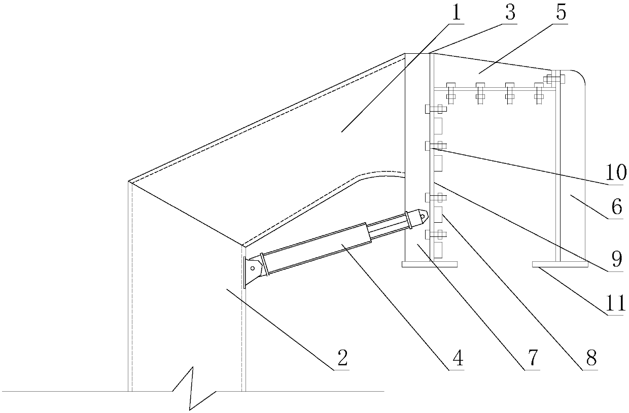
[0025] Such as figure 1As shown, the beam column for empty iron that facilitates the assembly of the track beam includes a column and an installation section 3 connected to the upper end of the column. The installation section 3 is used to connect the track beam, and the installation section 3 includes an installation plate 7, a first connection Plate 5 and the second connecting plate 6, one end of the first connecting plate 5 joins with the upper end of the mounting plate 7, the other end of the first connecting plate 5 joins with the upper end of the second connecting plate 6, the first connecting plate 5, The second connecting plate 6 and the mounting plate 7 form a doorframe shape, and the doorframe-shaped structure encloses a door-shaped space for installing the track beam, and the first connecting plate 5 is used as a crossbeam of the doorframe-shaped structure. Bolt holes 10 for realizing the bolt connection between the track beam and the installation section 3 are also...
Embodiment 2
[0030] Such as figure 1 As shown, this embodiment is further limited on the basis of Embodiment 1: at least one of the second connecting plate 6 and the mounting plate 7 is provided with a bolt hole for bolting the mounting section 3 to the track beam 10. The first connecting plate 5 is provided with bolt holes 10 for bolting the mounting section 3 to the track beam. In this scheme, the bolt holes 10 on both the second connecting plate 6 and the mounting plate 7 are used to install the connecting bolts used for horizontal positioning of the track beam on the beam column, and the bolt holes 10 on the first connecting plate 5 It is used to install the connecting bolts used for the vertical positioning of the track beam on the beam column. The axial direction of the bolt holes 10 on the connecting plate 5 is located in the vertical direction. In this way, after the connecting bolts are installed in the above bolt holes 10, the connecting bolts can be pulled as much as possible d...
Embodiment 3
[0040] Such as figure 1 As shown, this embodiment is further limited on the basis of the technical solution provided in Embodiment 1: in this embodiment, the surface of the door-shaped space includes a mounting surface 9 that is the surface of the second connecting plate 6, and the mounting surface 9 is a vertical surface, and at the same time, the first connecting plate 5 and the mounting plate 7 are integrally formed or welded, and a plurality of strip-shaped ribs 8 are fixed on the vertical surface, and the strip-shaped ribs 8 The length direction is along the extension direction of the track beam. Like this, adopt this scheme, after the track beam outer side is provided with the groove corresponding to bar-shaped rib 8, when finishing track beam and this beam column assembly, at first do not connect the second connecting plate 6 on the first connecting plate 5, by The side or end faces of the first connecting plate 5 and the mounting plate 7 are inserted into the track be...
PUM
 Abstract
Description
Claims
Application Information
 - R&D Engineer
- R&D Manager
- IP Professional
- Industry Leading Data Capabilities
- Powerful AI technology
- Patent DNA Extraction
Browse by: Latest US Patents, China's latest patents, Technical Efficacy Thesaurus, Application Domain, Technology Topic, Popular Technical Reports.
© 2024 PatSnap. All rights reserved.Legal|Privacy policy|Modern Slavery Act Transparency Statement|Sitemap|About US| Contact US: help@patsnap.com