
Clarification tank used for treating wastewater in photovoltaic industry

A wastewater treatment and clarifier technology, applied in water/sewage treatment, water/sludge/sewage treatment, flocculation/sedimentation water/sewage treatment, etc., can solve the problem of slow reaction speed, low efficiency of wastewater treatment, and sludge backflow and other problems, to achieve the effect of thorough mixing, improvement of wastewater treatment efficiency, and rapid flocculation

Pending Publication Date: 2018-05-18
WUXI DEPPEL WATER INVESTMENT
View PDF0 Cites 5 Cited by
  • Summary
  • Abstract
  • Description
  • Claims
  • Application Information

AI Technical Summary

Problems solved by technology

In the prior art, the medicament required for the reaction in the clarification tank is usually added to the wastewater in the tank through the dosing pipe, and then under the agitation of the stirring device, the wastewater in the tank and the medicament are continuously contacted and fused and reacted. In this way, whether the medicament can be quickly integrated into the wastewater of the whole pool depends entirely on the water flow speed after the agitation device is stirred, that is, the agitator needs to be agitated continuously at full power, but the diffusion effect of the medicament in the wastewater is not significant. Not very ideal, the reaction speed is slow, resulting in sludge reflux and poor flocculation effect
The wastewater treatment efficiency of the mechanically stirred clarifier is not high

Method used


Image

  • Clarification tank used for treating wastewater in photovoltaic industry
  • Clarification tank used for treating wastewater in photovoltaic industry

Examples


Embodiment Construction

[0019] The preferred embodiments of the present invention will be described in detail below in conjunction with the accompanying drawings, so that the advantages and features of the present invention can be more easily understood by those skilled in the art, so as to define the protection scope of the present invention more clearly.

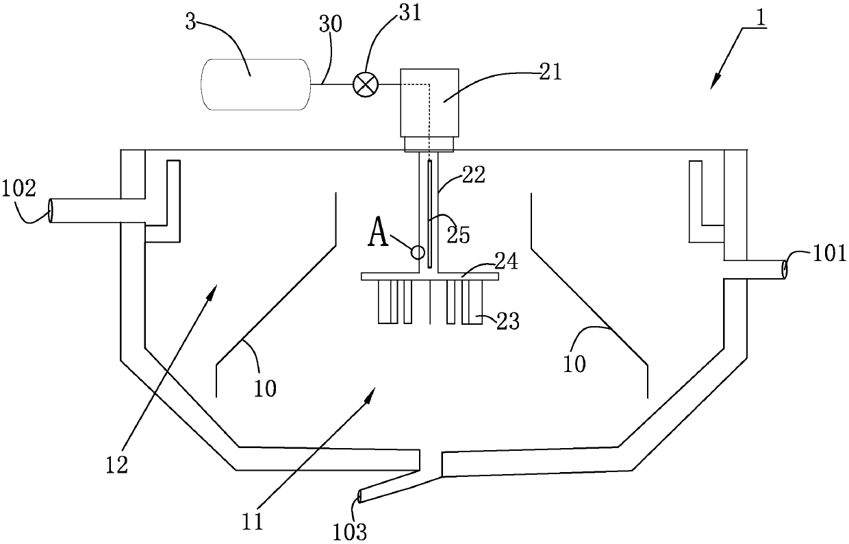
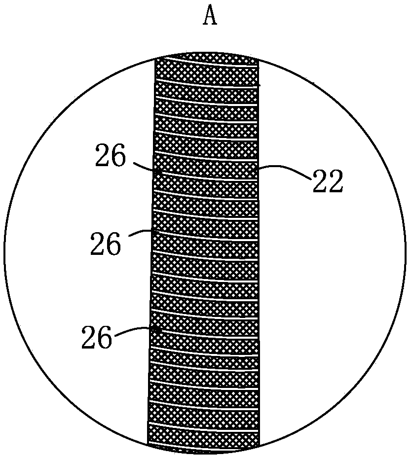
[0020] as attached figure 1 and figure 2 As shown, the present embodiment provides a clarification tank for wastewater treatment in the photovoltaic industry. The clarification tank includes a tank body 1 with a water inlet 101, a water outlet 102 and a sludge discharge port 103, and a stirring tank on the tank body 1. The mechanical agitation and lifting system for the wastewater in the pool body 1, and the drug supply system 3 for supplying chemicals to the wastewater in the pool body 1; a reaction chamber 11 and a separation chamber 12 that communicate with each other are formed inside the pool body 1, and the drug supply system 3 passes thro...


PUM


Abstract

The invention relates to a clarification tank used for treating wastewater in photovoltaic industry. The clarification tank includes a tank body provided with a water inlet, a water outlet, and a sludge discharging port, a mechanical stirring lifting system arranged on the tank body and used for stirring wastewater in the tank body, and an agent supply system for supplying an agent to wastewater located in the tank body. The tank body is internally provided with a reaction chamber and a separation chamber that communicate with each other. The agent supply system communicates with the mechanical stirring lifting system via an agent supply pipe. The mechanical stirring lifting system includes a stirring mechanism, a stirring motor, and an agent spraying structure that is arranged on the stirring mechanism and used for spraying an agent supplied by the agent supply system to wastewater located in the tank body. In the clarification tank, an original agent supply system communicates with the mechanical stirring lifting system to completely mix wastewater located in the tank body with the agent, so that the reaction is fast fully performed, the flocculation is fast, and the wastewater treatment efficiency of the clarification tank is greatly improved. The state that the motor is tired of rotation is improved.

Description

technical field [0001] The invention relates to a clarification tank for photovoltaic industry wastewater treatment. Background technique [0002] At present, the clarification equipment used for water treatment in the photovoltaic industry mainly includes: mechanical stirring clarifier tank, suspension clarifier tank and water conservancy circulation clarifier tank, these three clarifier tanks (see the water supply and drainage design manual No. Booklet - Urban Water Supply, Chapter 7, Section 7.3 Clarification). The clarification principle of the mechanical agitation clarifier is: through the action of mechanical agitation, the sludge in the first reaction chamber is refluxed and reacted with the raw water after dosing, and continues to react in the second reaction chamber to form larger flocs. Enter the clarification chamber through the diversion chamber for sedimentation and separation; specifically, the mechanical agitation clarification tank is a combination of the mi...

Claims


Application Information

Patent Timeline
Patent Type & Authority Applications(China)
IPC IPC(8): C02F1/52B01F7/18B01F15/02
CPCC02F1/5281B01F27/11251B01F27/2122B01F27/90B01F35/7179B01F2101/305
Inventor 陈晓东
Owner WUXI DEPPEL WATER INVESTMENT
Learn More