Die machining clamp

A mold processing and fixture technology, applied in workpiece clamping devices, metal processing equipment, metal processing mechanical parts, etc., can solve the problems of increasing the difficulty of operation by operators, the mold does not meet the production standards, and the mold direction adjustment is inconvenient. Increase the stability of connection and installation, ensure the diversity of structural levels, and improve the effect of overall stability

Inactive Publication Date: 2018-05-18
孙柳英
View PDF0 Cites 11 Cited by
  • Summary
  • Abstract
  • Description
  • Claims
  • Application Information

AI Technical Summary

Problems solved by technology

Before the mold is used, it is often necessary to process the mold, and it needs to be clamped during the mold processing, but at present, most of the clamping of the mold is clamped by a manipulator. The manipulator can only clamp the surface of the mold, and the mold is often in the process of processing. Movement occurs, so that the processed mold does not m

Method used


Image

  • Die machining clamp
  • Die machining clamp
  • Die machining clamp

Examples


Embodiment Construction

[0019] In order to further understand the invention content, characteristics and effects of the present invention, the following embodiments are listed below, and detailed descriptions are as follows in conjunction with the accompanying drawings.

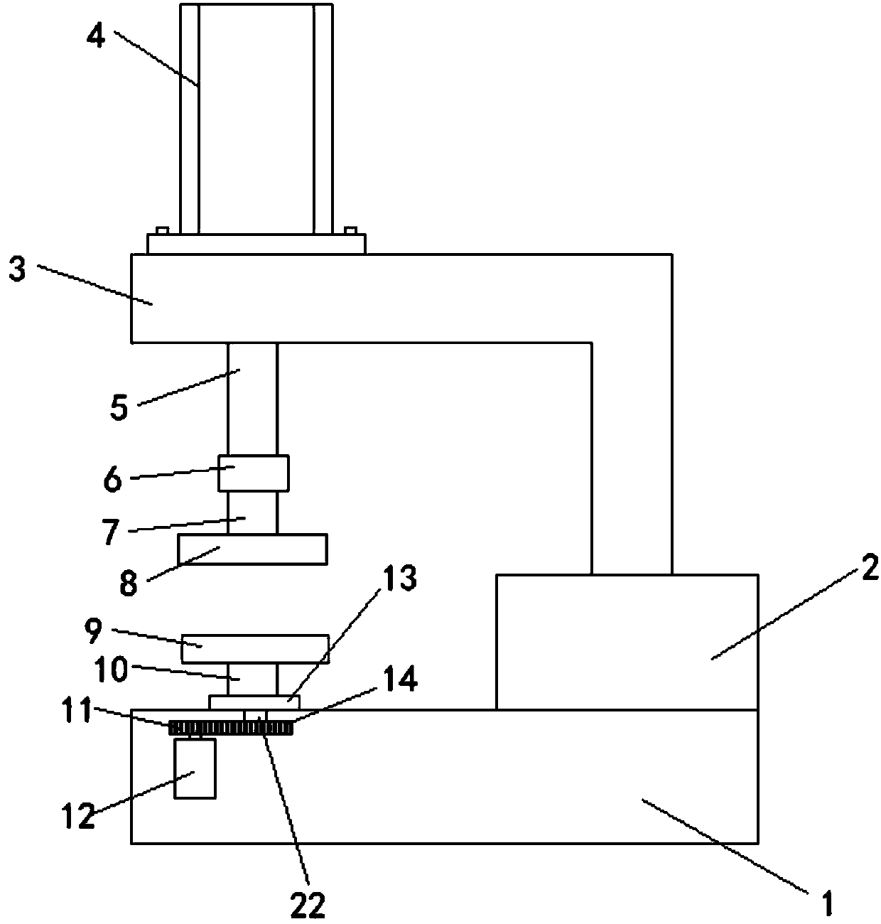
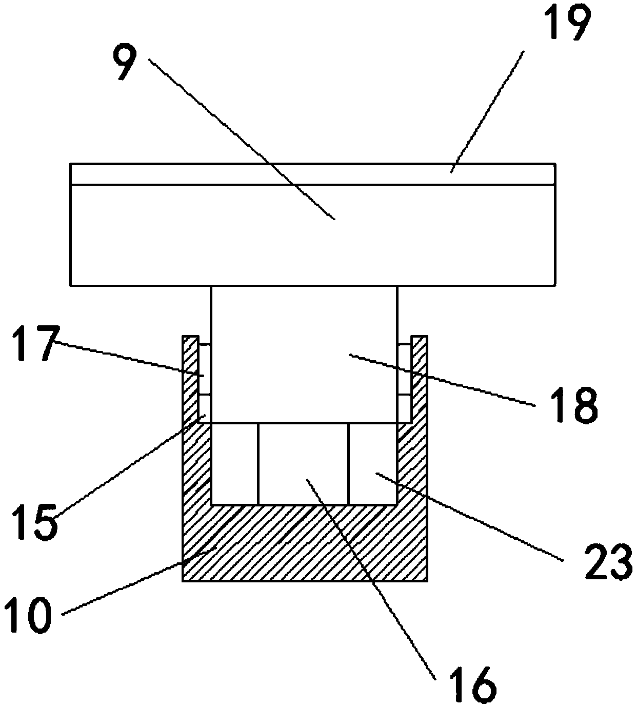
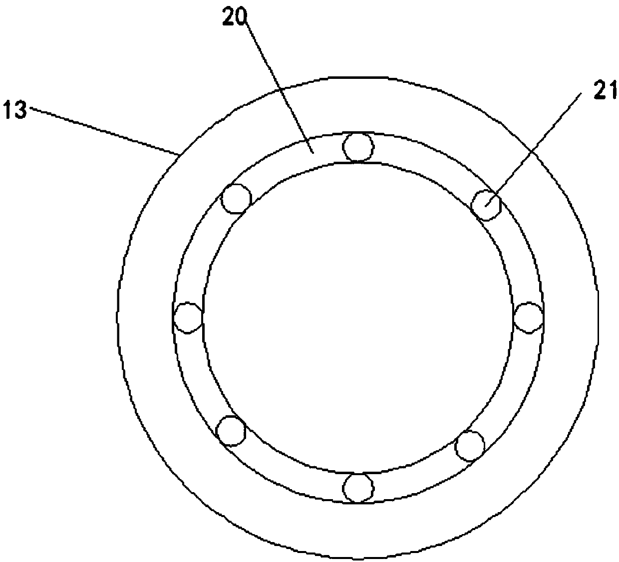
[0020] Combine below Figure 1-3 A detailed description of the mold processing fixture structure of the present invention: a mold processing fixture, including a workbench 1, a control box 2, a bracket 3, a cylinder 4, a piston rod 5, a bearing 6, an upper clamping block 8, a support rod 10, Motor 12, limit groove 15, pressure sensor 16 and connection block 18, described control box 2 is arranged at the middle position of workbench 1 side, and described control box 2 is fixedly connected with workbench 1, and described control box 2 The upper surface is provided with a support 3, the support 3 is fixedly connected with the control box 2 by welding, the support 3 is set to an L-shaped support, the upper end of the support 3 is provid...


PUM


Abstract

The invention relates to a die machining clamp. The die machining clamp includes a working table, a control box, a support and an air cylinder, the control box is arranged at the central position of one side of the working table, and the support is fixedly connected at the upper surface of the control box. According to the die machining clamp, an upper clamping block and a lower clamping block arearranged, the upper clamping block is rotatably connected with a piston rod through a bearing, and the lower clamping block is fixedly connected with a turntable through a support rod; during machining, a motor drives the turntable to rotate to achieve the rotation of the die, operation staff can conveniently machine the die thoroughly, and the work efficiency is improved; and the support rod isfurther arranged, a pressure sensor is arranged in an internal groove of the support rod, a connecting block is arranged above the pressure sensor, and the connecting block is fixedly connected with alower clamping block; and when the piston rod presses downward, the pressure can be monitored by the pressure sensor in real time, and excessive pressure between the supper clamping block and the lower clamping block can be avoided in case of the damage of the die.

Description

technical field [0001] The invention belongs to the technical field of mold processing equipment, and in particular relates to a clamp for mold processing. Background technique [0002] Molds are various molds and tools used in industrial production for injection molding, blow molding, extrusion, die-casting or forging forming, smelting, stamping and other methods to obtain the required products. In short, a mold is a tool used to shape an object. This tool is composed of various parts, and different molds are composed of different parts. It mainly realizes the processing of the shape of the article through the change of the physical state of the formed material, known as the "mother of industry". Before the mold is used, it is often necessary to process the mold, and it needs to be clamped during the mold processing, but at present, most of the clamping of the mold is clamped by a manipulator. The manipulator can only clamp the surface of the mold, and the mold is often in...

Claims


Application Information

Patent Timeline
IPC IPC(8): B23Q3/08B25B11/00B23Q17/00
CPCB23Q3/08B23Q17/00B25B11/00
Inventor 孙柳英
Owner 孙柳英
Why Eureka
Try Eureka