Insect trapping lamp for pond
A technology for trapping insect lamps and ponds, which is applied in the field of lighting. It can solve the problems of LED design without considering waterproof and heat dissipation, the influence of breeding living organisms, and the poor effect of flukes, etc., and achieve good lighting effects, good heat dissipation effects, and good water resistance.
- Summary
- Abstract
- Description
- Claims
- Application Information
AI Technical Summary
Problems solved by technology
Method used
Image
Examples
Embodiment 1
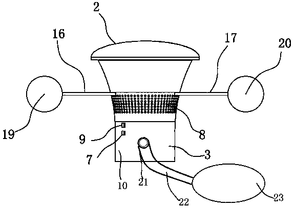
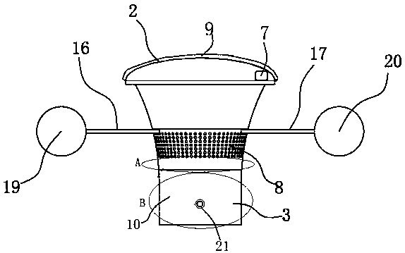
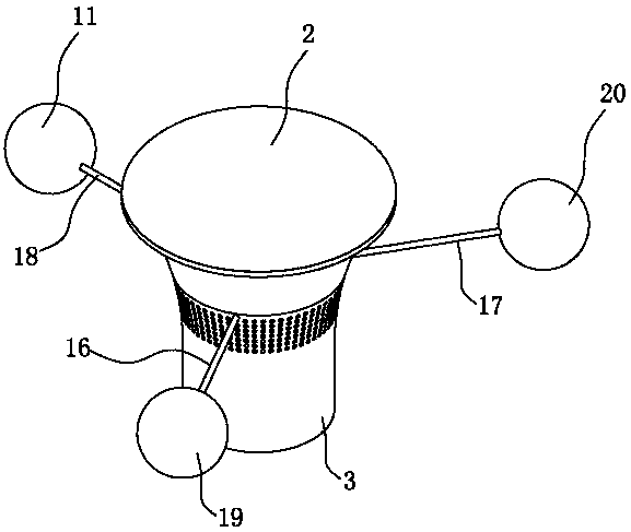
[0036] Such as figure 1 , image 3 and Figure 5 As shown, a kind of pond insect trap lamp of the present invention, described pond insect trap lamp comprises LED lamp 1, lamp body shell 2, base 3, motor 4, mounting seat 5 that can lift up and down, trapping hole 8, first A pole 16, a second pole 17, a third pole 18, an external power supply 9 and a collection device 10, the bottom of the lamp housing 2 is respectively provided with a first pole 16, a second pole 17 and a third pole Rod 18, the angle between the first pole 16, the second pole 17 and the third pole 18 is 120°, the top of the first pole 16 is provided with a first floating ball 19, the The top of the second pole 17 is provided with a second floating ball 20, and the top of the third pole 18 is provided with a third floating ball 11, and the three floating balls allow the bug-catching lamp to float on the water.
[0037]The bottom of the base 3 is provided with a collection device 10, the upper center of the b...
Embodiment 2
[0049] The difference between embodiment 2 and embodiment 1 is: as Figure 2 to Figure 5 As shown, a pond insect trap lamp of the present invention, the bottom of the base 3 is provided with a collection device 10, the upper center of the base 3 is provided with a mounting seat 5, and the upper part of the mounting seat 5 is provided with There is a motor 4, an LED lamp 1 is arranged on the top of the motor, the outer surface of the LED lamp 1 is provided with a waterproof inner cover forming the first cavity 6, and the lower end of the outer wall of the lamp body shell 2 is provided with an external connection The power supply 9 and the outlet 21, the upper end of the outer wall of the lamp housing 2 is provided with a trap hole 8, the motor 4 is arranged inside the first cavity 6, and the battery 7 is fixed on the upper part of the base 3 , the external power supply 9 is connected to the motor 4, the LED lamp 1 and the storage battery 7 respectively.
[0050] The collection...
Embodiment 3
[0054] The difference between embodiment 3 and embodiment 1 is that the thickness of the light-emitting layer is 1 mm.
[0055] Although this article uses 1 LED lamp, 2 lamp body shell, 3 base, 4 motor, 5 mounting base, 6 first cavity, 7 battery, 8 trapping hole, 10 collecting device, 11 third floating ball, 12 Second cavity, 13 sliding rail, 14 sliding groove, 15 base drive cylinder, 16 first rod, 17 second rod, 18 third rod, 19 first floating ball, 20 second floating ball, 21 row Terms such as outlet, 22 storage bags, 23 water pipes, but do not exclude the possibility of using other terms. These terms are used only for the purpose of describing and explaining the essence of the present invention more conveniently; interpreting them as any kind of additional limitation is against the spirit of the present invention.
PUM
| Property | Measurement | Unit |
|---|---|---|
| Thickness | aaaaa | aaaaa |
| Thickness | aaaaa | aaaaa |
| Thickness | aaaaa | aaaaa |
Abstract
Description
Claims
Application Information
 - R&D
- Intellectual Property
- Life Sciences
- Materials
- Tech Scout
- Unparalleled Data Quality
- Higher Quality Content
- 60% Fewer Hallucinations
Browse by: Latest US Patents, China's latest patents, Technical Efficacy Thesaurus, Application Domain, Technology Topic, Popular Technical Reports.
© 2025 PatSnap. All rights reserved.Legal|Privacy policy|Modern Slavery Act Transparency Statement|Sitemap|About US| Contact US: help@patsnap.com


