Test marking machine with code scanning device

A technology for marking and installing grooves, applied in the field of testing marking machines, can solve the problems of inability to contact the detection probe, low overall efficiency and quality, and marking of qualified products, so as to be suitable for mass production, easy to track and count, and detect. The effect of high efficiency and automation

Pending Publication Date: 2018-05-15
JIANGSU A KERR BIOLOGICAL RECOGNITION TECH CO LTD
View PDF0 Cites 0 Cited by
  • Summary
  • Abstract
  • Description
  • Claims
  • Application Information

AI Technical Summary

Problems solved by technology

[0002] Fingerprint chips usually need to be tested in factory quality inspection, recycled product inspection, and performance testing. Usually, the detection fixture includes a fixture base plate with a detection circuit, a detection base fixed on the fixture base plate, and a fixture base plate on the fixture base plate. Set the detection probe connected to the detection circuit and matched with the electronic chip; when testing, place the chip on the detection base, and the detection probe should touch the detection point of the corresponding chip. Generally, the upper end of the chip is simply pressed by a pressing block The chip or sometimes the chip is welded on the detection base, so that the chip is close to the detection probe for detection. However, the chip is easily misplaced on the detection base, and the insufficient force on the upper end of the chip will easily cause some parts to not be in contact with the detection probe. This leads to inaccurate test results. In addition, after the test is completed, it is necessary to manually mark the qualified products.
This method involves a lot of manual work, and there are still problems such as missed printing and low defect detection rate, and the management is not standardized, difficult to identify, and the overall efficiency and quality are low; therefore, it is necessary to improve the existing inspection mechanism and improve its quality. Automation level, reduce labor intensity, improve inspection quality and production efficiency

Method used


Image

  • Test marking machine with code scanning device
  • Test marking machine with code scanning device
  • Test marking machine with code scanning device

Examples


Embodiment 1

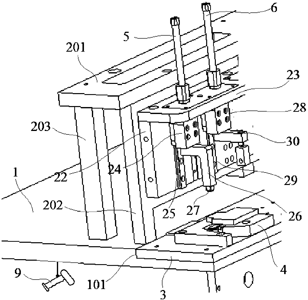
[0027] Embodiment 1: A test marking machine with a code scanning device, including a base 1, a bracket 2, a substrate 3, a test carrier 4, a test cylinder 5, a dotting cylinder 6 and a code scanning device 9, and the bracket 2 is installed on the base 1 upper surface, the base plate 3 is embedded in the installation groove 101 on one side of the base 1 and fixedly connected with the base 1, the test carrier 4 is installed on the upper surface of the base plate 3 by several bolts and is located under the test cylinder 5, the sweeper The code device 9 is installed on the base 1 through a support bracket 902;

[0028]The support bracket 902 is installed on the lower surface of the base 1, and the support bracket 902 is provided with a horizontal installation groove 909, and a motor 910 is fixedly installed in the installation groove 909, and the output end of the motor 910 is fixedly connected to There is a rotating shaft 911, the end of the rotating shaft 901 is fixedly connecte...

Embodiment 2

[0034] Embodiment 2: A test marking machine with a code scanning device, including a base 1, a bracket 2, a substrate 3, a test carrier 4, a test cylinder 5, a dotting cylinder 6 and a code scanning device 9, and the bracket 2 is installed on the base 1 upper surface, the base plate 3 is embedded in the installation groove 101 on one side of the base 1 and fixedly connected with the base 1, the test carrier 4 is installed on the upper surface of the base plate 3 by several bolts and is located under the test cylinder 5, the sweeper The code device 9 is installed on the base 1 through a support bracket 902;

[0035] The support bracket 902 is installed on the lower surface of the base 1, and the support bracket 902 is provided with a horizontal installation groove 909, and a motor 910 is fixedly installed in the installation groove 909, and the output end of the motor 910 is fixedly connected to There is a rotating shaft 911, the end of the rotating shaft 901 is fixedly connect...


PUM


Abstract

The invention discloses a test marking machine with a code scanning device. The test marking machine comprises a base, a bracket, a substrate, a testing carrying table, a testing air cylinder, a dotting air cylinder and a scanning device, wherein the testing carrying table is mounted on the upper surface of the substrate through a plurality of bolts and is located below the testing air cylinder, the scanning device is mounted on the base through a support frame, and the support frame is mounted on the lower surface of the base; the lower end of a pull rope penetrates through a through hole andis connected with the scanning device, an insertion rod matched with an insertion hole is inserted into the support frame corresponding to the position of a connecting block, a push handle is fixedlyconnected to the insertion rod located outside the support frame, a plurality of through holes for PIN needles to insert are formed in the support plate and the base, the PIN needles are sequentiallyembedded into the through holes of the support plate and the base; and one end, far from a translation mechanism, of a movable baffle is fixedly connected with the surface on the side of a mounting plate through bolts. The test marking machine has the advantages that the detection is accurate, the detection efficiency and the automation degree are high, and the test marking machine is suitable for large-batch production.

Description

technical field [0001] The invention relates to a device testing device, in particular to a test marking machine with a code scanning device. Background technique [0002] Fingerprint chips usually need to be tested in factory quality inspection, recycled product inspection, and performance testing. Usually, the detection fixture includes a fixture base plate with a detection circuit, a detection base fixed on the fixture base plate, and a fixture base plate on the fixture base plate. Set the detection probe connected to the detection circuit and matched with the electronic chip; when testing, place the chip on the detection base, and the detection probe should touch the detection point of the corresponding chip. Generally, the upper end of the chip is simply pressed by a pressing block The chip or sometimes the chip is welded on the detection base, so that the chip is close to the detection probe for detection. However, the chip is easily misplaced on the detection base, an...

Claims


Application Information

Patent Timeline
IPC IPC(8): G01R31/28G06K17/00H01L21/67
CPCG06K17/0022H01L21/67282G01R31/2887
Inventor 陈东王海昌陈松姚燕杰王凯姜海光
Owner JIANGSU A KERR BIOLOGICAL RECOGNITION TECH CO LTD
Why Eureka
Try Eureka