
Test device with code scanning device

A testing device and code scanning technology, which is applied in the direction of measuring devices, electronic circuit testing, measuring electricity, etc., to achieve the effects of improving the correct identification rate, convenient tracking and statistics, high detection efficiency and high degree of automation

Inactive Publication Date: 2018-06-19
JIANGSU A KERR BIOLOGICAL RECOGNITION TECH CO LTD
View PDF3 Cites 0 Cited by
  • Summary
  • Abstract
  • Description
  • Claims
  • Application Information

AI Technical Summary

Problems solved by technology

[0002] As people's requirements for information security are getting higher and higher, traditional digital passwords or Jiugongge passwords can no longer meet people's requirements for information security

Method used


Image

  • Test device with code scanning device
  • Test device with code scanning device
  • Test device with code scanning device

Examples


Embodiment 1

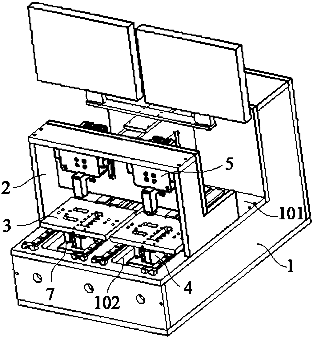
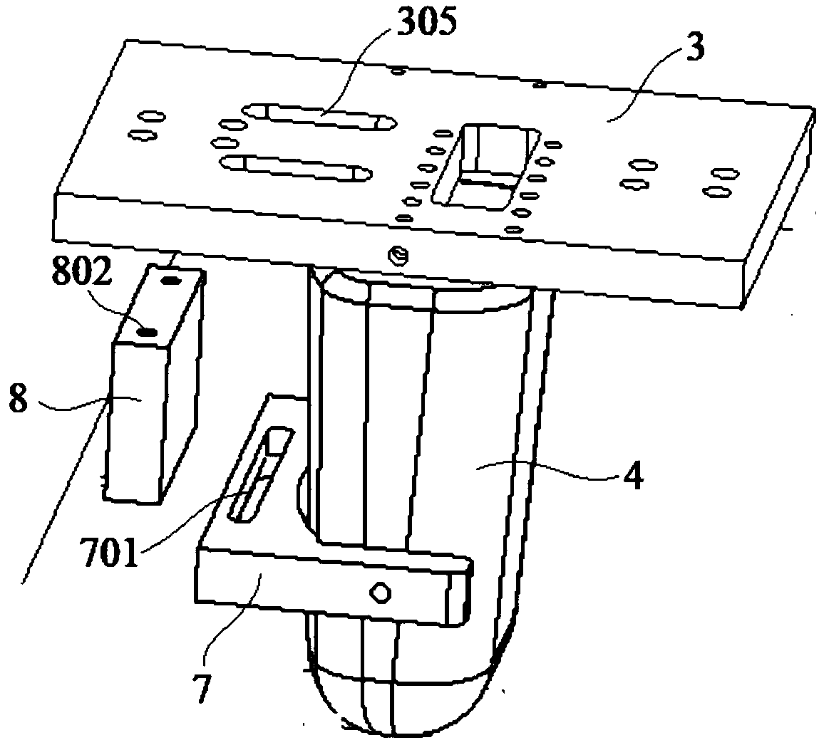
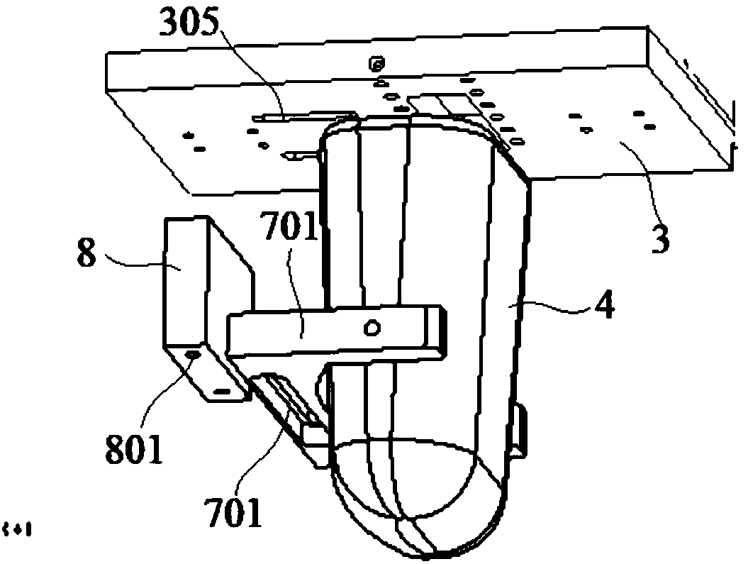
[0026] Embodiment 1: A test device with a code scanning device, including a base case 1, a bracket 2 installed on the upper surface of the base case 1, a test platform 3, a code scanning device 4 and a test mechanism 5, the test platform 3 Installed on the upper surface of the cover plate 101 of the base box 1, the test mechanism 5 is fixedly connected with the bracket 2 and located above the test platform 3, and the cover plate 101 of the base box 1 is provided with a passageway for the code scanning device 4 to be embedded. Hole 102, the code scanning device 4 is embedded in the through hole 102 of the cover plate 101 of the base box 1 and is fixedly connected to the lower surface of the test platform 3 through a mounting frame 7;

[0027] The mounting frame 7 is U-shaped, the code scanning device 4 is embedded in the U-shaped groove of the mounting frame 7 and is fixedly connected with the mounting frame 7, and the mounting frame 7 is connected with the test carrier 3 throug...

Embodiment 2

[0032] Embodiment 2: A test device with a code scanning device, including a base case 1, a bracket 2 installed on the upper surface of the base case 1, a test platform 3, a code scanning device 4 and a test mechanism 5, the test platform 3 Installed on the upper surface of the cover plate 101 of the base box 1, the test mechanism 5 is fixedly connected with the bracket 2 and located above the test platform 3, and the cover plate 101 of the base box 1 is provided with a passageway for the code scanning device 4 to be embedded. Hole 102, the code scanning device 4 is embedded in the through hole 102 of the cover plate 101 of the base box 1 and is fixedly connected to the lower surface of the test platform 3 through a mounting frame 7;

[0033] The mounting frame 7 is U-shaped, the code scanning device 4 is embedded in the U-shaped groove of the mounting frame 7 and is fixedly connected with the mounting frame 7, and the mounting frame 7 is connected with the test carrier 3 throug...


PUM


Abstract

The invention discloses a test device with a code scanning device, which comprises a base box, a support arranged on the upper surface of the base box, a test carrier platform, a code scanning deviceand a test mechanism, wherein the test carrier platform is arranged on the upper surface of a cover plate of the base box; a bar-shaped mounting hole is opened in the mounting support; the lower surface of an adjusting plate is provided with a plurality of round mounting holes; two sides of a through hole in the upper cover plate of the base box is provided with guide rails; the lower surface of the test carrier platform is provided with sliding blocks for enabling the guide rails to be embedded; a left side plate and a right side plate are arranged at two sides of the upper surface of the test carrier platform; a beam plate crosses between the left side plate and the right side plate and is fixed on the upper surfaces of the left side plate and the right side plate; one ends of two connection blocks are fixedly connected with the surfaces of two sides of a push plate, and the other ends pass through the bar-shaped through holes in the rear side plate to be fixedly connected with the side surface of a movable plate; and a test head is fixedly connected with the movable plate through a mounting block. Through the arrangement of a rubber test head, certain flexibility is realized, proper pressure can be provided, and a product can be prevented from being pressed damaged due to over large pressure.

Description

technical field [0001] The invention relates to a device testing device, in particular to a testing device with a code scanning device. Background technique [0002] As people's requirements for information security are getting higher and higher, traditional digital passwords or Jiugongge passwords can no longer meet people's requirements for information security. Biometric identification is widely used in new-generation electronic devices, and the stability and uniqueness of fingerprints make fingerprint identification devices widely used. [0003] Fingerprint chips usually need to be tested during factory quality inspection, recycled product inspection, and performance inspection. Usually, manual inspections are required one by one, and then the defective products are sorted out, and the good products are then packaged. Contents of the invention [0004] The object of the present invention is to provide a test device with a code scanning device. The test device with a c...

Claims


Application Information

Patent Timeline
Patent Type & Authority Applications(China)
IPC IPC(8): G01R31/28G06K7/00
CPCG01R31/2851G06K7/00
Inventor 陈东王海昌陈松姚燕杰王凯姜海光
Owner JIANGSU A KERR BIOLOGICAL RECOGNITION TECH CO LTD
Learn More