Liquid crystal display assembly

A liquid crystal display and component technology, applied in the direction of instruments, optical components, polarizing components, etc., can solve problems such as water leakage, bulky cooling components, and the need for regular water replacement

Inactive Publication Date: 2018-05-11
STRUCTO
View PDF6 Cites 0 Cited by
  • Summary
  • Abstract
  • Description
  • Claims
  • Application Information

AI Technical Summary

Problems solved by technology

However, water cooling has disadvantages including water leakage, the need for periodic water changes, and bulky cooling components

Method used


Image

  • Liquid crystal display assembly
  • Liquid crystal display assembly
  • Liquid crystal display assembly

Examples


Embodiment Construction

[0030] Embodiments of the present invention attempt to actively maintain the temperature of the liquid crystal panel at the panel's specific operating temperature, especially in situations where the LCD cannot directly use conventional cooling methods, namely conduction and convection.

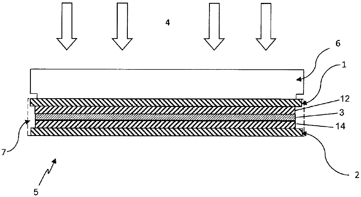
[0031] Referring to Figure 1, there is shown a prior art LCD assembly 5 having an LCD panel 7 secured to a rigid platform 6 that is transparent to electromagnetic radiation from the UV spectrum to the infrared spectrum. The platform 6 may be any material that is sufficiently rigid to prevent structural buckling on the LCD glass 12, 14 when the assembly is subjected to a vertical load. The LCD panel 7 includes a first polarizer 1 disposed on a first substrate 12 . The first substrate 12 and the second substrate 14 sandwich the liquid crystal material layer 3 . The second polarizer 2 is provided on the second substrate 14 . The first base plate 12 and the second base plate 14 serve to provide ...


PUM


Abstract

A liquid crystal display assembly, comprises: a first substrate, a second substrate and a liquid crystal layer intermediate the first substrate and the second substrate; a first polarizer having an inner surface which faces towards the first substrate, and an outer surface; and a second polarizer disposed on the second substrate and having a plane of polarization orthogonal to that of the first polarizer; wherein the inner surface of the first polarizer is spaced from the first substrate such that the inner surface and / or the outer surface is exposed to enable convective cooling thereof.

Description

technical field [0001] The present invention relates to liquid crystal display (LCD) assemblies and methods of arranging components of an LCD assembly. Embodiments are useful in applications such as LCD-based projectors and stereolithography equipment, but it should be appreciated that the invention may be used in other contexts as well. Background technique [0002] Liquid crystal displays (LCDs) typically include a liquid crystal material sandwiched between a pair of glass filters. Each glass filter has a sheet of polarizing material disposed thereon. The plates have respective polarization planes perpendicular to each other. [0003] Polarizers used in LCDs are typically absorbing polarizers, for example composed of iodine-doped PVA. This provides a high extinction ratio and therefore high contrast. Due to this property of the polarizer, the amount of light absorbed by the polarizer increases proportionally as the intensity of the radiation used to backlight the LCD i...

Claims


Application Information

Patent Timeline
IPC IPC(8): G02F1/13G02F1/1335G02B5/30G03B21/16B33Y30/00
CPCB33Y30/00G02B5/3033G02F1/133385G02F1/133528G03B21/16B29C64/00F26B3/28F26B3/30G02F1/133382G03B21/006G02F1/133531
Inventor 许贝特斯·特奥多鲁斯·彼得鲁斯·万艾斯布勒克德万什·夏尔马兰修洪陈卡法
Owner STRUCTO
Why Eureka
Try Eureka