Multi-layer tubular bus structure
A busbar structure, multi-layer tube technology, applied in conductors, insulated cables, electrical components, etc., can solve the problem that the layout and arrangement are difficult to take into account current carrying, heat dissipation, material saving, and the strength of multi-layer busbars is limited by application. , to achieve the requirements of mass production, solve the uneven electric field, and solve the effect of heat dissipation
- Summary
- Abstract
- Description
- Claims
- Application Information
AI Technical Summary
Problems solved by technology
Method used
Image

Examples
Embodiment 1
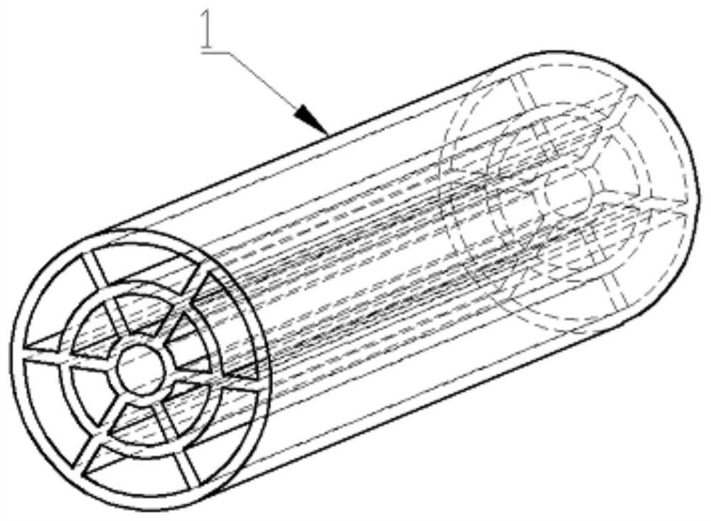
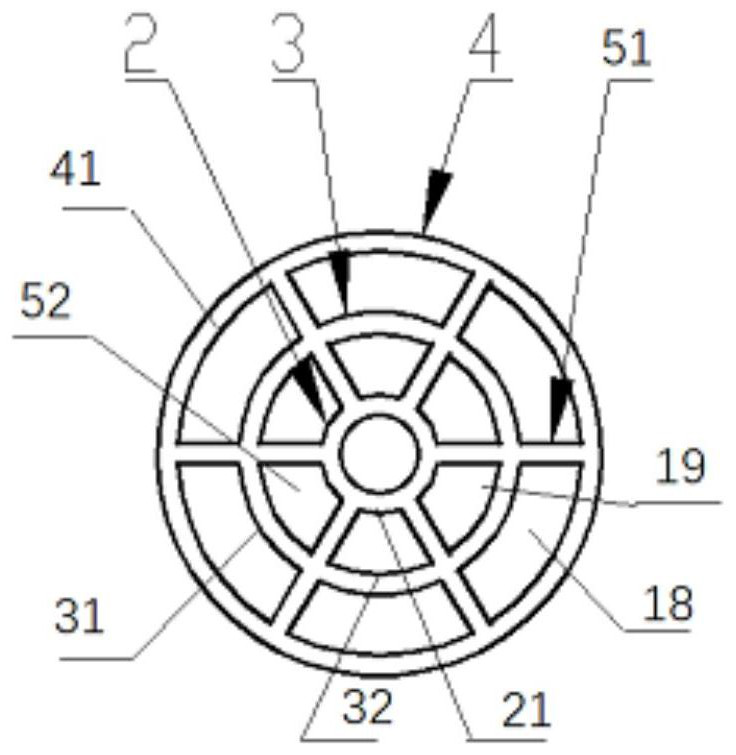
[0032] Such as figure 1 The multi-layer tubular busbar structure 1 shown in or 2 includes an outer tubular busbar 4 arranged on the outermost layer and an inner tubular busbar 2 concentrically arranged with the outer tubular busbar 4, between the outer tubular busbar 4 and the inner tubular busbar 2 An intermediate pipe busbar 3 is provided. Such as figure 2 As shown, the outer pipe busbar 4, the middle layer pipe busbar 3 and the inner pipe busbar 2 are all tubular structures.
[0033] Six first support members 51 are arranged between the inner wall 41 of the outer pipe busbar 4 and the outer wall 31 of the middle layer pipe busbar 3 .
[0034] Six second support members 52 are arranged between the inner wall 32 of the middle pipe busbar 3 and the outer wall 21 of the inner pipe busbar 2 .
[0035] Both the first support member 51 and the second support member 52 are arranged on the radial line of the axis of the multi-layer tubular busbar structure. The first space 18 b...
Embodiment 2
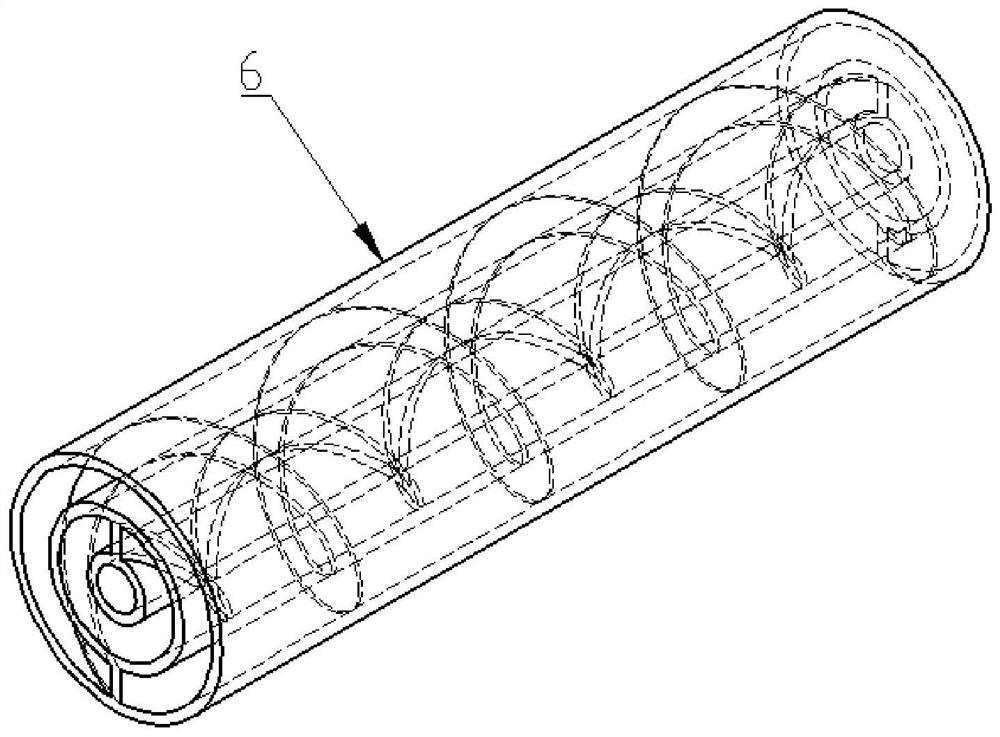
[0038] Such as image 3 Or the multi-layer tubular busbar structure 6 shown in 4 includes an outer tubular busbar 9 arranged on the outermost layer and an inner tubular busbar 7 concentrically arranged with the outer tubular busbar 9, between the outer tubular busbar 9 and the inner tubular busbar 7 An intermediate pipe busbar 8 is provided. Such as Figure 4 As shown, the outer pipe busbar 9, the middle layer pipe busbar 8 and the inner pipe busbar 7 are all tubular structures.
[0039] A first support member 11 is provided between the inner wall 91 of the outer pipe busbar 9 and the outer wall 81 of the middle layer pipe busbar 8 .
[0040] A second support member 10 is provided between the inner wall 82 of the middle layer pipe busbar 8 and the outer wall 71 of the inner pipe busbar 7 .
[0041] The first space 20 between the inner wall 91 of the outer pipe busbar 9 and the outer wall 81 of the intermediate pipe busbar 8 is set into a helical space structure with a hoof-...
Embodiment 3
[0044] Such as Figure 5 Or the multi-layer tubular busbar structure 12 shown in 6 includes an outer tubular busbar 15 arranged on the outermost layer and an inner tubular busbar 13 concentrically arranged with the outer tubular busbar 15, between the outer tubular busbar 15 and the inner tubular busbar 13 An intermediate pipe busbar 14 is provided. Such as Image 6 As shown, the outer pipe busbar 15, the middle layer pipe busbar 14 and the inner pipe busbar 13 are all tubular structures.
[0045] A first support member 17 is disposed between the inner wall 151 of the outer pipe bus bar 15 and the outer wall 141 of the middle layer pipe bus bar 14 .
[0046] A second support member 16 is disposed between the inner wall 142 of the middle layer pipe busbar 14 and the outer wall 131 of the inner pipe busbar 13 .
[0047] The first space 22 between the inner wall 151 of the outer pipe busbar 15 and the outer wall 141 of the middle layer pipe busbar 14 is divided into several cu...
PUM
 Abstract
Description
Claims
Application Information
 - R&D
- Intellectual Property
- Life Sciences
- Materials
- Tech Scout
- Unparalleled Data Quality
- Higher Quality Content
- 60% Fewer Hallucinations
Browse by: Latest US Patents, China's latest patents, Technical Efficacy Thesaurus, Application Domain, Technology Topic, Popular Technical Reports.
© 2025 PatSnap. All rights reserved.Legal|Privacy policy|Modern Slavery Act Transparency Statement|Sitemap|About US| Contact US: help@patsnap.com