
Feeding device and metal plate cutting machine

A gold cutting machine and cutting device technology, applied in metal processing equipment, welding equipment, laser welding equipment and other directions, can solve the problems of low production efficiency, large power consumption, large floor space, etc., to improve the overall production efficiency, Improve feeding efficiency and save floor space

Pending Publication Date: 2018-05-11
SHENZHEN H TECH CO LTD
View PDF0 Cites 7 Cited by
  • Summary
  • Abstract
  • Description
  • Claims
  • Application Information

AI Technical Summary

Problems solved by technology

[0003] Most of the existing sheet metal laser cutting machines use independent large-scale hammocks to lift the sheet metal, which not only consumes a lot of power, but also occupies a large area, and the actions are complicated and time-consuming, resulting in low production efficiency.

Method used


Image

  • Feeding device and metal plate cutting machine
  • Feeding device and metal plate cutting machine
  • Feeding device and metal plate cutting machine

Examples


Embodiment Construction

[0025] The following will clearly and completely describe the technical solutions in the embodiments of the present invention with reference to the accompanying drawings in the embodiments of the present invention. Obviously, the described embodiments are only part of the embodiments of the present invention, not all of them. Based on the embodiments of the present invention, all other embodiments obtained by persons of ordinary skill in the art without creative efforts fall within the protection scope of the present invention.

[0026] It should be noted that all directional indications (such as up, down, left, right, front, back...) in the embodiments of the present invention are only used to explain the relationship between the components in a certain posture (as shown in the accompanying drawings). Relative positional relationship, movement conditions, etc., if the specific posture changes, the directional indication will also change accordingly.

[0027] In addition, in t...


PUM


Abstract

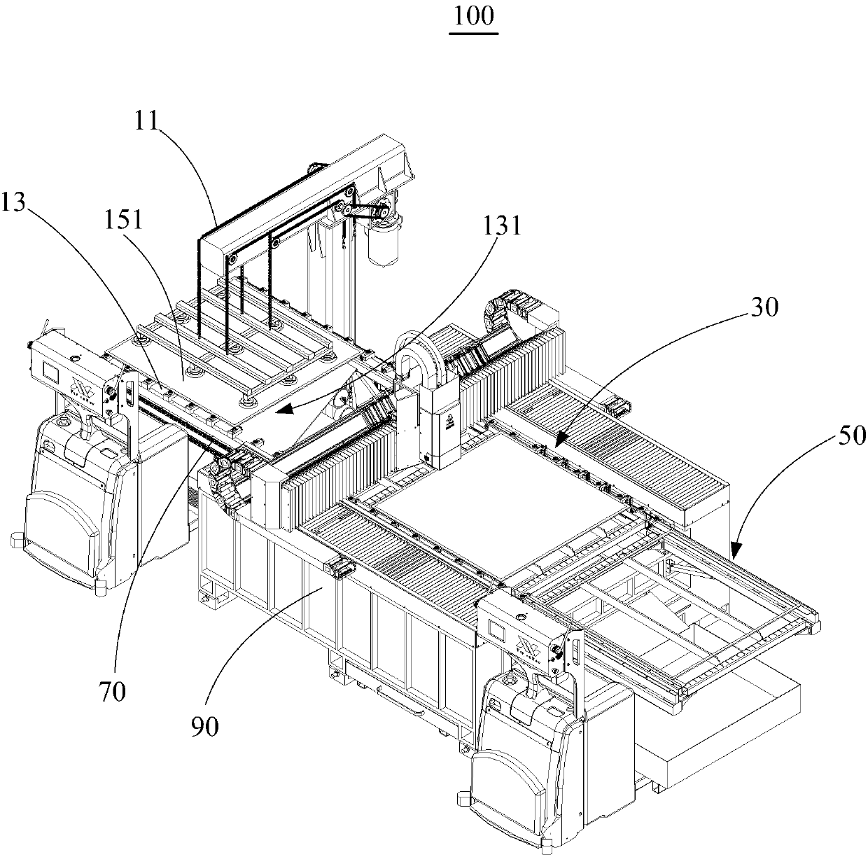
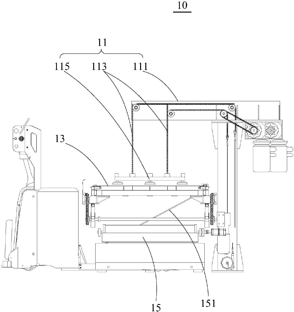
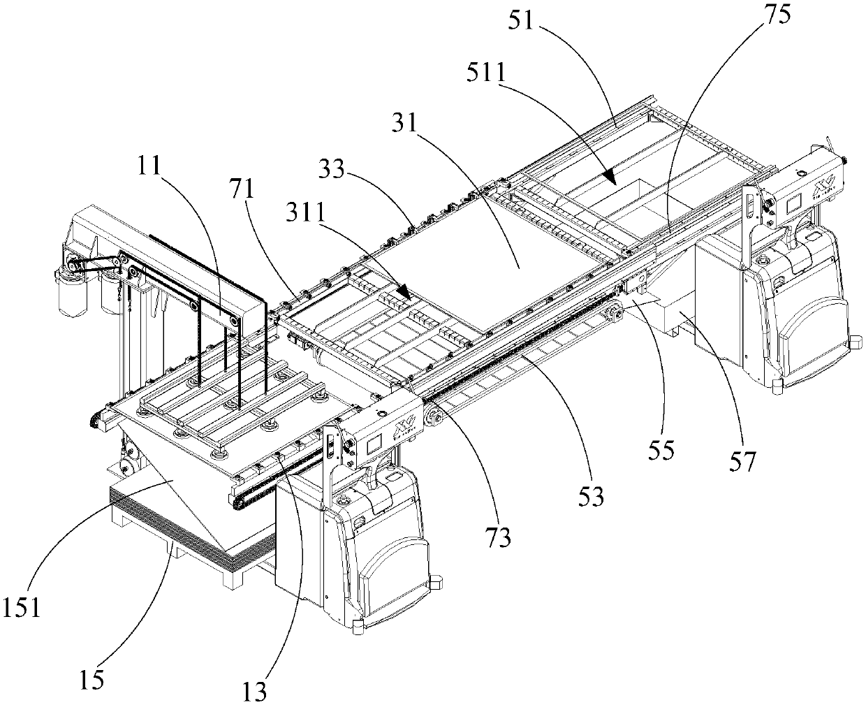
The invention discloses a feeding device and a metal plate cutting machine applying the same. The feeding device comprises a feeding mechanism and a feeding platform, wherein the feeding mechanism isarranged above the feeding platform, a material plate is arranged below the feeding platform, an abdication opening is formed in the feeding platform, the feeding mechanism penetrates through the abdication opening to do lifting motion in material taking, so that the material plate is put on the feeding platform. According to the technical scheme, the occupied area of the feeding device can be saved, and the feeding time can be saved, so that the production efficiency can be improved.

Description

technical field [0001] The invention relates to the technical field of sheet metal cutting machines, in particular to a feeding device and a sheet metal cutting machine using the feeding device. Background technique [0002] Laser cutting sheet metal is to focus the laser emitted from the laser into a high-power-density laser beam through the optical path system. The laser beam irradiates the surface of the sheet metal workpiece to make it reach the melting point or boiling point. The molten or vaporized metal is blown away, and with the movement of the relative position of the workpiece at the speed of light, the material will eventually form a kerf, so as to achieve the purpose of cutting. Laser cutting uses laser beams instead of traditional mechanical knives. It has the advantages of high precision, fast cutting, smooth incision, and low processing cost. It will gradually replace traditional metal cutting equipment. [0003] Most of the existing sheet metal laser cuttin...

Claims


Application Information

Patent Timeline
Patent Type & Authority Applications(China)
IPC IPC(8): B23K26/70B23K26/38
CPCB23K26/38B23K26/702
Inventor 岳国汉
Owner SHENZHEN H TECH CO LTD
Learn More