A flue gas mixing device and method

A technology of flue gas mixing and flue, which is applied in the direction of mixing method, gas and gas/steam mixing, mixer, etc., can solve the problems of poor flue gas mixing effect and high energy consumption, and solve the problem of poor flue gas mixing effect , Solve the effect of high energy consumption and reduce collision loss

Active Publication Date: 2019-08-13
INST OF PROCESS ENG CHINESE ACAD OF SCI
View PDF12 Cites 0 Cited by
  • Summary
  • Abstract
  • Description
  • Claims
  • Application Information

AI Technical Summary

Problems solved by technology

[0007] The purpose of the present invention is to provide a flue gas mixing device and method to solve the problems of high energy consumption and poor flue gas mixing effect of the existing flue gas mixing device

Method used


Image

  • A flue gas mixing device and method
  • A flue gas mixing device and method
  • A flue gas mixing device and method

Examples


Embodiment Construction

[0036] The technical solutions of the present invention will be further described below in conjunction with the accompanying drawings and through specific implementation methods.

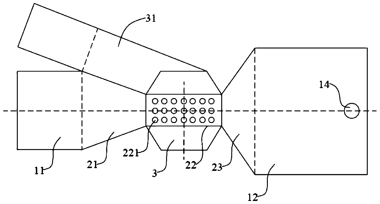
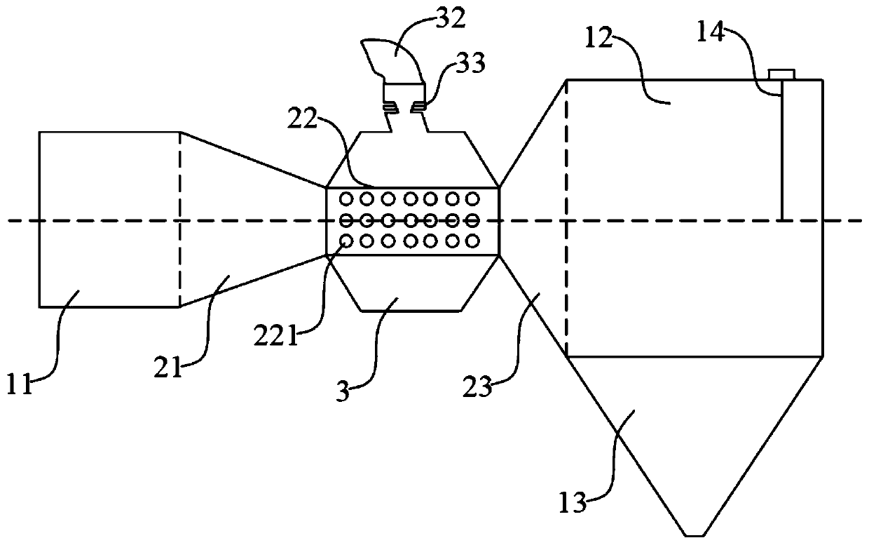
[0037] Such as figure 2 as shown, figure 2 It is a top view of a flue gas mixing device provided in this embodiment (the air branch pipe is not shown in the figure). The main body of the flue gas mixing device is a Venturi tube structure, and the flue inlet section 11, Neck section 21 , throat section 22 , flaring section 23 and flue outlet section 12 . The air intake holes 221 are evenly and obliquely arranged on the circumferential side wall of the throat section 22 , and the throat section 22 extends outward in the circumferential direction with a ring cavity 3 covering the entire throat section 22 Outside, a space for containing gas is formed inside the ring cavity 3 . The cross-section of the ring cavity 3 can be a circular structure or a trapezoidal structure. This embodiment does not lim...


PUM

PropertyMeasurementUnit
angleaaaaaaaaaa
angleaaaaaaaaaa

Abstract

The invention discloses a flue gas mixing device and method, and relates to the technical field of gas mixing. The flue gas mixing device includes a flue inlet section, a throat section and a flue outlet section connected in sequence, the side wall ring of the throat section is provided with a plurality of air inlet holes, and the outer periphery of the throat section is provided with a ring cavity , the ring channel cavity is connected with a ring-cooled exhaust gas branch pipe. In the present invention, the main body of the flue gas mixing device is designed as a Venturi tube structure, so that when the circulating flue gas flows into the throat section, the annular cooling exhaust gas can be accelerated and drained, and the annular cooling exhaust gas can be ensured without being pressurized by the annular cooling fan. It can be fully mixed into the circulating flue, and the ring-cooled exhaust gas passes through the ring cavity and the air intake hole successively, which can also play a drainage role for the circulating flue gas, thus solving the problem of high energy consumption and flue gas mixing of the existing flue gas mixing device Problem with poor performance.

Description

technical field [0001] The invention relates to the technical field of gas mixing, in particular to a flue gas mixing device and method. Background technique [0002] The sintering flue gas circulation process refers to a sintering method in which a part of the heat-carrying gas discharged from the sintering process is returned to the trolley after the sintering igniter for recycling. A sintering flue gas waste heat graded recycling and pollutant emission reduction process and system (CN201510140855.9), a method and device for sintering low-temperature waste heat circulation and exhaust gas reduction (CN200910051731.8), and an energy-saving and environment-friendly sintering waste gas waste heat The sintering flue gas circulation process involved in the utilization and pollutant purification process and system (CN201410309084.7) and other related patents all propose that in order to ensure the quality of sintered minerals in the flue gas cycle, sufficient oxygen should be en...

Claims


Application Information

Patent Timeline
Patent Type & Authority Patents(China)
IPC IPC(8): B01F5/04B01F3/02B01F23/10
CPCB01F23/10B01F25/312F27D17/004F27B21/00B01F25/31242B01F25/31425B01F35/2132B01F35/2202
Inventor 朱廷钰徐文青李超群
Owner INST OF PROCESS ENG CHINESE ACAD OF SCI
Why Eureka
Try Eureka