A load-balanced redundant switching system in which the control board and the switching board bus are directly connected

A load balancing and switching system technology, applied in the field of wireless communication, can solve problems such as increased power consumption and delay, increased cost, limited network communication bandwidth, etc., to achieve the effect of reducing network delay, increasing network bandwidth, and avoiding multiple conversions

Active Publication Date: 2020-07-21
BEIJING INST OF COMP TECH & APPL
View PDF12 Cites 0 Cited by
  • Summary
  • Abstract
  • Description
  • Claims
  • Application Information

AI Technical Summary

Problems solved by technology

There are two defects in this solution: the bandwidth of network communication is limited by the network card, and when the load balancer is deployed as the main road, it will often become a network bottleneck; there is a single node failure, and redundant equipment needs to be purchased during deployment, which increases the cost
There are two defects in this solution: the data communication between the two circuit boards undergoes multiple signal conversions, which increases power consumption and delay; the device has a single node failure, and redundant devices need to be purchased during deployment, which increases the cost

Method used


Image

  • A load-balanced redundant switching system in which the control board and the switching board bus are directly connected
  • A load-balanced redundant switching system in which the control board and the switching board bus are directly connected

Examples


Embodiment Construction

[0019] In order to make the purpose, content, and advantages of the present invention clearer, the specific implementation manners of the present invention will be further described in detail below in conjunction with the accompanying drawings and embodiments.

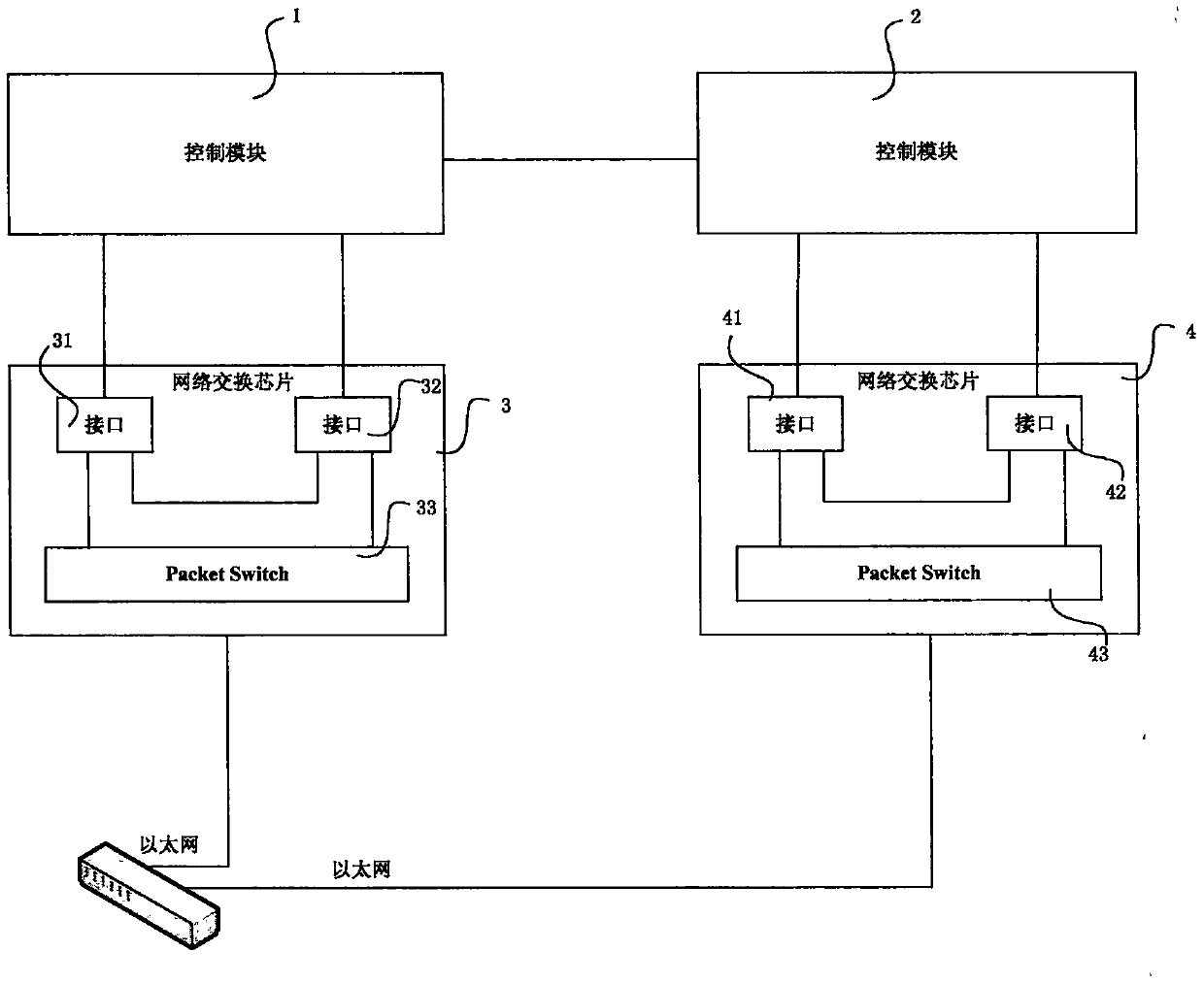
[0020] figure 1 Shown is the block diagram of the load balancing redundant switching system directly connected to the control board and the switching board bus of the present invention, as figure 1 As shown, the load-balancing redundant switching system in which the control board and the switching board bus are directly connected in the present invention mainly includes: two load balancer control / switching circuits. It specifically includes: a control module 1 , a control module 2 , a network switch chip 3 , and a network switch chip 4 . The network switch chip 3 includes an interface 31 , an interface 32 and a packet switch 33 . The network switching chip 4 includes: an interface 41 , an interface 42 and a packet sw...


PUM


Abstract

The present invention discloses a load balance redundancy switching system of a control panel directly connected with a switch board bus. The system comprises: a first interface being a PCIe externalinterface of a first switch board; a second interface being a PCIe internal interface of a first switch board; a third interface being a PCIe external interface of a second switch board; a fourth interface being a PCIe internal interface of a second switch board; a first control module and a second control module which are respectively configured to perform output of the input PCIe data after loadbalance, wherein the first control module and the second control module are redundant to each other to allow the first switch board and the second switch board to form a redundant structure; and a first grouping switch and a second grouping switch which are respectively configured switch the PCIe data and Ethernet data to communicate with an external Ethernet. The load balance redundancy switching system of the control panel directly connected with the switch board bus avoid multi-time conversion of data signals, reduce the network delay and increase the network bandwidth.

Description

technical field [0001] The invention relates to the technical field of wireless communication, in particular to a dual-channel fusion emergency video encrypted wireless transmission device. Background technique [0002] With the vigorous development of Internet technologies such as clustering and cloud computing, application delivery load balancers have become a common four-layer / seven-layer network load balancing device in data center applications. There are two common implementations of this load balancing device: [0003] The first is to integrate a dedicated network card or a high-speed Ethernet card on the control board circuit board, and achieve the purpose of data flow load balancing through specific software and drivers. There are two defects in this solution: the bandwidth of network communication is limited by the network card, and when the load balancer is deployed as the main road, it will often become a network bottleneck; there is a single node failure, and re...

Claims


Application Information

Patent Timeline
Patent Type & Authority Patents(China)
IPC IPC(8): G05B19/042
CPCG05B19/0421G05B2219/24182
Inventor 邹昀辛刘丰杨帆王晓光李云祥
Owner BEIJING INST OF COMP TECH & APPL
Why Eureka
Try Eureka