Confocal microscope mode aberration correction device

A confocal microscope and aberration technology, applied in the field of devices for improving confocal imaging quality and resolution, and aberration correction devices, can solve the problems of complex sample preprocessing steps, inconvenient operation, and complex aberration correction devices, etc. The effect of device simplification, imaging quality improvement, and imaging amplitude improvement

Active Publication Date: 2020-07-28
HARBIN INST OF TECH +1
View PDF4 Cites 0 Cited by
  • Summary
  • Abstract
  • Description
  • Claims
  • Application Information

AI Technical Summary

Problems solved by technology

[0003] The purpose of the present invention is to provide a confocal microscope mode aberration correction device to solve the problems that the existing aberration correction device is too complicated, inconvenient to operate and the sample pretreatment steps are complicated

Method used


Image

  • Confocal microscope mode aberration correction device

Examples


Embodiment Construction

[0015] Preferred embodiments of the present invention will be described in detail below with reference to the accompanying drawings.

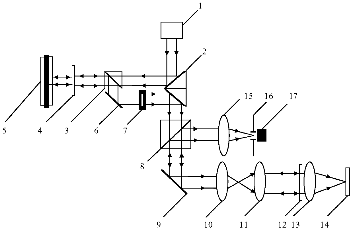
[0016] Such as figure 1 As shown, the confocal microscope mode aberration correction device of the present invention includes a laser 1, a double-sided 45° mirror 2, a beam splitter 3, a half-wave plate 4, a spatial light modulator 5, a mirror 6, and a diaphragm 7. Polarizing beam splitter 8, XY scanning galvanometer 9, scanning lens 10, tube mirror 11, objective lens 12, 1 / 4 wave plate 13, collecting lens 15, optical fiber aperture 16 and photomultiplier tube 17;

[0017] The laser light emitted by the laser 1 is reflected by one side of the double-sided 45° reflector 2 and then reaches the half-wave plate 4 via the beam splitter 3, and then enters the spatial light modulator 5 after being modulated by the half-wave plate 4. After being modulated by the spatial light modulator 5, it is sent back to the beam splitter 3, and then reflected to t...


PUM


Abstract

The invention relates to a mode aberration correction device for a confocal microscope, belonging to the technical fields of adaptive optics and confocal microimaging. According to the mode aberrationcorrection device, the problems that an existing aberration correction device is too complex and inconvenient to operate, and sample pretreatment steps of are complex are solved. Laser emitted by a laser device is reflected by a light reflection mirror surface on one side of a double-surface 45-degree light reflection mirror, arrives at a half-wave plate through a beam splitter, is modulated by the beam splitter, is incident into a spatial light modulator, is modulated by the spatial light modulator, is returned to the beam splitter and is reflected to a reflection mirror by the beam splitter; and after high-order diffraction stray light is filtered through a diaphragm, the light is emitted to a light reflection mirror surface on the other side of the light reflection mirror, is reflectedby the double-surface 45-degree light reflection mirror again and is emitted to an XY scanning galvanometer through a polarization beam splitter. According to the mode aberration correction device for the confocal microscope, the image amplitude can be increased by 44% under the conditions that the sample operation is not increased and the imaging device is the simplest, and the imaging quality is increased by 17.

Description

technical field [0001] The invention relates to an aberration correction device, in particular to a device for improving the quality and resolution of confocal imaging by using the aberration correction device, and belongs to the technical fields of adaptive optics and confocal microscopic imaging. Background technique [0002] The confocal microscope system has the advantages of high resolution and three-dimensional depth imaging. Its high-resolution characteristics require the focal spot size to be close to the diffraction limit to obtain the best theoretical resolution. However, the assembly error of the optical system and the surface deviation of the optical components will cause aberrations, resulting in distortion of the focal spot and a decrease in resolution. It is necessary to dynamically correct the aberrations generated by these optical systems and improve the imaging quality. At present, there is no simple and practical aberration correction device for confocal mi...

Claims


Application Information

Patent Timeline
Patent Type & Authority Patents(China)
IPC IPC(8): G01N21/01G01N21/21
CPCG01N21/01G01N21/21
Inventor 刘辰光赵唯松刘俭陈刚王宇航谭久彬
Owner HARBIN INST OF TECH
Why Eureka
Try Eureka