
Current collector of energy storage cell for storing electrical energy

An energy storage battery, a technology for storing electric energy, applied in the field of current collectors, can solve the problem of high cost

Active Publication Date: 2018-05-01
ROBERT BOSCH GMBH
View PDF9 Cites 0 Cited by
  • Summary
  • Abstract
  • Description
  • Claims
  • Application Information

AI Technical Summary

Problems solved by technology

Such current collectors are therefore designed in the form of grids and thus result in a complex electrode production, which is in contradiction to the fact that almost all energy storage cells to be produced industrially are produced by film casting in the roll-to-roll process

Method used


Image

  • Current collector of energy storage cell for storing electrical energy
  • Current collector of energy storage cell for storing electrical energy

Examples


Embodiment Construction

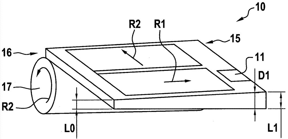
[0034] figure 1 A current collector 10 for an electrochemical energy storage cell (not shown) constructed according to a first embodiment of the invention is shown. The current collector 10 has a contact area called a tab 11 arranged on a first end 15 of two mutually opposite ends 15 , 16 of the current collector 10 . In addition, the label 11 is also provided for connecting the current collector 10 to a pole or poles of the same polarity of the energy storage battery.

[0035] The current collector 10 is constructed in the form of layers with a layer thickness D1 that can vary along the first direction R1 . Here, the course of the layer thickness D1 along the first direction R1 corresponds to a monotonically or strictly monotonically increasing distance from the second of the two ends 15 , 16 16 (not explicitly characterized) the first function of . The first direction R1 extends from the second end 16 to the first end 15 and runs perpendicularly to the layer thickness D1 ...


PUM


Abstract

The present invention relates to a current collector of an energy storage cell for storing electrical energy. The present invention relates to a current collector (10) of an energy storage cell for storing electrical energy. The current collector (10) has a contact area referred to as a tab (11) which is disposed on a first end of two opposite ends (15, 16) of the current collector (10), and configured for connecting the current collector (10) to one electrode or more common electrodes of the energy storage cell. The current collector (10) is designed in the form of a layer with a variable layer thickness (D1) in a first direction (R1). A change course of the layer thickness (D1) in the first direction (R1) corresponds to a monotonically increasing or severely and monotonically increasingfirst function with increasing distance to a second end of the two ends (15, 16). The first direction (R1) extends from the second end (16) to the first end (15) and is perpendicular to the layer thickness (D1). The distance to the second end (16) extends in the first direction (R1).

Description

technical field [0001] The invention relates to a current collector for an energy storage battery for storing electrical energy. Furthermore, the invention relates to an energy storage battery for storing electrical energy, said energy storage battery having at least one such current collector. Background technique [0002] Energy storage batteries for storing electrical energy, such as lithium-ion batteries, hybrid supercapacitors and ultracapacitors, are known from the prior art. Such energy storage cells comprise a thin electrode layer coated on a flat current collector. The electrode layers are each configured as an anode layer or a cathode layer. The current collectors are each constructed in the form of layers with a constant layer thickness and each have a contact region called a tab. Labels of such current collectors are provided for connecting the corresponding current collector to the pole or poles of the corresponding energy storage cell. In lithium-ion batter...

Claims


Application Information

Patent Timeline
Patent Type & Authority Applications(China)
IPC IPC(8): H01M4/64H01M4/70H01G11/66H01G11/70
CPCH01G11/66H01G11/70H01M4/64H01M4/70H01M4/78H01M10/0525H01M2004/029H01G11/10H01G11/74Y02E60/10Y02P70/50
Inventor S.哈恩
Owner ROBERT BOSCH GMBH
Learn More