
A kind of preparation method of engine cover

An engine cover and generating agent technology, which is applied to other household appliances, household appliances, household components, etc., can solve the problems of high temperature and humidity requirements, difficulty in ensuring thickness uniformity, and affecting the user's appearance and feeling, etc. Achieve the effect of high production efficiency, high qualification rate, low requirements and investment

Active Publication Date: 2020-10-16
芜湖飞利汽车零部件有限公司
View PDF8 Cites 0 Cited by
  • Summary
  • Abstract
  • Description
  • Claims
  • Application Information

AI Technical Summary

Problems solved by technology

Although the soft engine cover made of polyurethane integral skin foam has a certain impact cushioning effect after colliding with pedestrians, however, during the pouring process, the soft engine cover is prone to trachoma or dark bubbles due to the need for lightweight Defects make the product yield poor and affect the appearance of the user; in addition, the back of the engine cover will produce a correspondingly thinner skin, resulting in poor sound-absorbing effect
Spraying the skin and then performing foam molding on it has high requirements on the temperature and humidity of the entire operating environment; especially for products with complex product surfaces, it is difficult to ensure uniform thickness; and it causes a large waste of raw materials

Method used


Image

  • A kind of preparation method of engine cover
  • A kind of preparation method of engine cover
  • A kind of preparation method of engine cover

Examples


preparation example Construction

[0075] The invention provides a method for preparing an engine cover.

[0076]

[0077] A kind of preparation method of engine cover, such as figure 1 As shown, it includes the following steps:

[0078] (1) Inject the skin forming agent from the closed sprue of the upper mold of the first mold into the cavity of the first mold, cure for 60-90s, and then open the upper mold of the first mold and the lower mold of the first mold , to obtain the upper cortex 1 with a wavy surface;

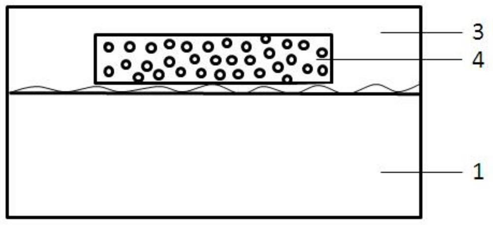
[0079] (2), place the non-wavy surface of the cortex 1 with the wavy surface on the inner bottom surface of the second mold, make the non-wavy surface contact with the inner bottom surface, and have the cortex 1 wave of the wavy surface at the top Place the micro-perforated plate 2 with a support on the surface, then pour the foam layer generator on the corrugated surface of the cortex 1 with a corrugated surface and the micro-perforated plate 2 with a support to form a foam layer 3, and close the...

Embodiment 1

[0156] The present embodiment provides a kind of preparation method of engine cover, as figure 1 As shown, it includes the following steps:

[0157] (1) Inject the skin forming agent from the sprue of the upper mold of the closed first mold (the injection pressure is 11MPa) into the cavity of the first mold, solidify for 60s, and then open the upper mold of the first mold and the second mold. A lower mold of a mold, to obtain a cortex 1 with a wavy surface on the upper part;

[0158] (2), place the non-wavy surface of the cortex 1 with the wavy surface on the inner bottom surface of the second mold, make the non-wavy surface contact with the inner bottom surface, and have the cortex 1 wave of the wavy surface at the top Place the micro-perforated plate 2 with support on the surface, then pour (the pressure of pouring is 11MPa) foam layer generator to be formed foam layer 3, and close the upper mold of the second mold and the lower mold of the second mold to carry out foam mo...

Embodiment 2

[0213] The present embodiment provides a kind of preparation method of engine cover, as figure 2 As shown, it includes the following steps:

[0214] (1) Inject the skin forming agent from the sprue of the closed upper mold of the first mold (the injection pressure is 11MPa) into the cavity of the first mold, solidify for 90s, and then open the upper mold of the first mold and the second mold. A lower mold of a mold, to obtain a cortex 1 with a wavy surface on the upper part;

[0215] (2), place the non-wavy surface of the cortex 1 with the wavy surface on the inner bottom surface of the second mold, make the non-wavy surface contact with the inner bottom surface, and have the cortex 1 wave of the wavy surface at the top Place the micro-perforated plate 4 on the shaped surface, then pour (the pressure of pouring is 11MPa) foam layer generating agent on the wavy surface of the cortex 1 with the wavy surface and the micro-perforated plate 4 to form the foam layer 3, and close t...


PUM

PropertyMeasurementUnit
pore sizeaaaaaaaaaa
thicknessaaaaaaaaaa
pore sizeaaaaaaaaaa

Abstract

The invention provides a preparation method for an engine cover lid. The method comprises the following steps: after a skin layer generating agent is subjected to reaction and injection moulding, a skin layer with a wavy structure is obtained; a micro perforated plate is placed on the wavy surface of the skin layer, a foam layer generating agent is poured on the micro perforated plate, and mold closing is carried out; and after molding is performed, mold opening is carried out, and therefore the engine cover lid is obtained. The engine cover lid provided by the invention includes a foam layerand the skin layer covering the foam layer, wherein the foam layer is rich in foam and the micro perforated plate, so that noise generated by an engine can be better absorbed; the wavy surface of theskin layer can reflect the noise from the engine back to the foam layer, thereby prolonging the standing time of the noise in the foam layer, giving play to better sound-absorbing and noise-reducing effects, and facilitating acquirement of better mute of a cab; and at the same time, the non-wavy surface of the skin layer has a good appearance, so that the visual requirements of users can be met.

Description

technical field [0001] The invention belongs to the technical field of engine cover materials, and in particular relates to a preparation method of an engine cover. Background technique [0002] The engine cover is an auto accessory that covers the engine of the vehicle. Its surface in contact with the engine needs to have good sound absorption, so as to prevent the noise generated by the engine from spreading to the cockpit; its surface that is not in contact with the engine needs to have good sound absorption. In order to meet the user's appearance feeling. [0003] The current manufacturing process of the engine cover is divided into two types, one is to use a hard PP or PA injection-molded hard shell, and the back is covered with sound-absorbing materials to obtain a hard engine cover; the other is a soft engine cover, which is made of Made of one-time cast polyurethane integral skin foam. Although the soft engine cover made of polyurethane integral skin foam has a cer...

Claims


Application Information

Patent Timeline
Patent Type & Authority Patents(China)
IPC IPC(8): C08G18/66C08G18/32C08G18/38C08G18/40C08G18/48C08G18/50C08G18/63C08J9/08B29D99/00C08G101/00
CPCB29D99/006C08G18/3206C08G18/3814C08G18/4072C08G18/482C08G18/4837C08G18/5021C08G18/632C08G18/6674C08G18/6685C08G2110/0083
Inventor 史春朋程俊杰
Owner 芜湖飞利汽车零部件有限公司
Learn More