
Full-automatic sponge disc horizontal cutting machine

A flat cutting machine, fully automatic technology, applied in the field of flat cutting machines, can solve the problems of insufficient sponge weight, high labor intensity, reduced work efficiency, etc., and achieve the effects of high product accuracy, simple and convenient operation, and improved work efficiency.

Inactive Publication Date: 2018-05-01
宁波江北文增新材料科技有限公司
View PDF5 Cites 1 Cited by
  • Summary
  • Abstract
  • Description
  • Claims
  • Application Information

AI Technical Summary

Problems solved by technology

[0003] The platform of the existing flat cutting machine moves back and forth, and it is an empty stroke when moving backwards, which reduces the work efficiency; the movement of the existing flat cutting machine tool rest is driven by a common T-shaped threaded screw and an asynchronous motor, and the noise is large during movement. The precision is low; the sponge of the existing flat cutting machine is placed freely on the platform, and the friction between the sponge and the platform is completely determined by the weight of the sponge. In this way, the relative movement between the sponge and the platform is often caused by the insufficient weight of the sponge in the cutting density , resulting in inaccurate thickness; the upper and lower platforms of the sponge of the existing flat cutting machine are completely carried by hand, and the labor intensity of the workers is relatively high; the tightness of the existing flat cutting machine knife belt is also manually controlled, and the replacement of the knife belt takes a long time and is laborious

Method used


Image

  • Full-automatic sponge disc horizontal cutting machine
  • Full-automatic sponge disc horizontal cutting machine
  • Full-automatic sponge disc horizontal cutting machine

Examples


Embodiment Construction

[0027] The present invention will be described in further detail below by means of specific embodiments:

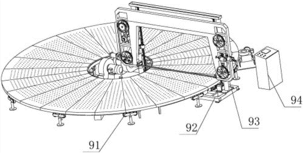
[0028] The reference signs in the accompanying drawings of the description include: platform 91, main frame 92, knife rest 93, electric control box 94, friction drive wheel 95, platen 96, inner ring 97, outer roller 98, suction platform 99, blowing platform 10. Suction fan 11, blower 12, column 13, sliding sleeve 14, hinge 15, ball screw 16, base 17, transmission shaft 18, angle adjustment part 19, beam 20, frame body 21, knife belt 22, knife Wheel 23, knife belt motor 24, pneumatic tensioning device 25, knife box 26, knife sharpening device 27, servo motor 28, reducer 29, reversing reducer 30, screw nut 31, cylinder support 32, cylinder joint 33 , slide rail 35, slide seat 36, bearing 37, reduction motor 38, rotary encoder 39, bearing 40, fixed seat 41, rotating arm 42, screw mandrel 45, first sprocket wheel 46, second sprocket wheel 47.

[0029] refer to figure 1 , ...


PUM


Abstract

The invention provides a full-automatic sponge disc horizontal cutting machine which comprises a platform and a main rack. The main rack is connected with a knife rest. A platform is horizontally place under the knife rest. The side face of the platform is provided with an electric control cabinet for controlling a plurality of motors on the main rack and the knife rest to work. The main rack is provided with a pneumatic tensioning device and an angle adjusting device. According to the horizontal cutting machine, the cut thickness and the number of cutting times are set on the electric controlcabinet, then the knife rest is moved to a proper position, a starting part on the electric control cabinet is pressed to drive a knife belt on the knife rest to operate, a friction drive wheel on the platform drives a table plate to rotate, and cutting work is completed. The device improves working efficiency of cutting sponge sheets, reduces thickness errors of the sponge sheets, improves the surface quality of the sponge sheets, and reduces work intensity of workers.

Description

technical field [0001] The invention relates to a flat cutting machine, in particular to a fully automatic sponge disc flat cutting machine. Background technique [0002] Existing flat cutting machines are generally composed of four parts: column, knife rest, platform and control box. When working, put the sponge on the platform, set the thickness to be cut on the control box, and then the control box controls the knife holder to move down the column to the set position according to the set thickness, and then the platform drives the sponge to move forward , the tool holder is horizontally set to a high-speed blade. When the sponge passes the knife holder, the high-speed blade will separate the sponge from top to bottom. When the platform moves to the front limit, the platform will automatically stop and then automatically move backwards. Move, stop when the platform moves to the rear limit, then the tool holder moves down to the set thickness, and then the platform moves f...

Claims


Application Information

Patent Timeline
IPC IPC(8): B26D1/48B26D3/28B26D7/01B26D7/06B26D7/12B26D7/14B26D7/20B26D7/22B26D7/26
CPCB26D1/48B26D3/28B26D7/018B26D7/06B26D7/12B26D7/14B26D7/20B26D7/22B26D7/2628
Inventor 项文增
Owner 宁波江北文增新材料科技有限公司
Learn More