
Clamping device for plate cutting

A technology of clamping device and plate, which is applied in the direction of positioning device, clamping, support, etc., can solve the problems of unfavorable company benefits, plate damage, plate falling off, etc., and achieve the effect of reducing manpower and convenient operation

Inactive Publication Date: 2018-05-01
陕西再造故乡文化发展有限公司
View PDF0 Cites 4 Cited by
  • Summary
  • Abstract
  • Description
  • Claims
  • Application Information

AI Technical Summary

Problems solved by technology

[0002] At present, the manufacturing industry is becoming more and more developed. In terms of sheet metal manufacturing, it is necessary to perform various processes on the sheet. When the sheet is dried and cut, it is necessary to put the large sheet on the carrier. If the sheet cannot be clamped, processing will occur. Mistakes, the plate falls off due to overturning or other reasons, causing damage to the plate, which is very detrimental to the company's benefits

Method used


Image

  • Clamping device for plate cutting
  • Clamping device for plate cutting

Examples


Embodiment Construction

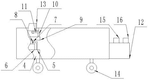
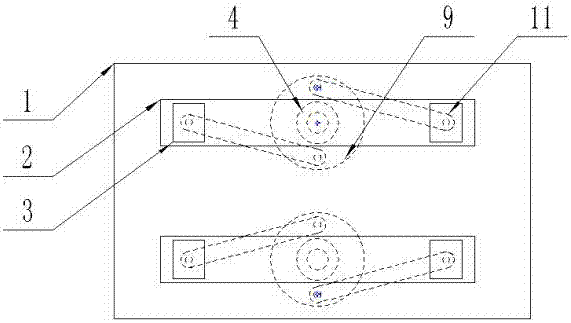
[0013] The present invention is specifically described below in conjunction with accompanying drawing, as Figure 1-2 As shown in the figure, a clamping device for sheet material cutting includes a base (1), and both ends of the outer upper surface of the base (1) are processed with rectangular openings (2), and the inside of the rectangular opening (2) is movable A set of clamping blocks (3) that can move inside it is embedded, and brackets (4) are fixedly welded at both ends of the inner lower surface of the base (1) and below the rectangular opening (2), and the brackets ( 4) The N-shaped frame (5) is installed with bolts on the outer upper surface, and the rotating motor (6) is fixedly installed inside the N-shaped frame (5), and the beams of the N-shaped frame (5) are all processed with circular Openings (7), the circular openings (7) are fixedly embedded with bearings (8), the rotating end of the rotating motor (6) is fixedly equipped with a disc (9), and the circumferen...


PUM


Abstract

The invention discloses a clamping device for plate cutting. The clamping device comprises a base. Rectangular openings are machined in the two ends of the upper surface of the outer portion of the base correspondingly, a set of clamping blocks capable of moving in each rectangular opening is movably installed in the rectangular opening in an embedded mode, supports are fixedly welded to the positions, located below the rectangular openings, of the two ends of the lower surface of the interior of the base correspondingly, N-shaped frames are installed on the upper surfaces of the outer portions of the supports in a bolted mode correspondingly, and rotating motors are fixedly installed in the N-shaped frames correspondingly; circular openings are machined in cross beams of the N-shaped frames correspondingly, bearings are fixedly installed in the circular openings in an embedded mode correspondingly, circular discs are fixedly installed at the rotating ends of the rotating motors correspondingly, and cylinders are fixedly welded to the opposite tangent points of the circumferential faces of the circular discs correspondingly; and rotating rods are fixedly installed on the cylindersin a sleeving mode correspondingly, the other ends of the rotating rods are connected with the lower surfaces of the clamping blocks through hinge pins correspondingly, a controller is fixedly installed on one side of the base, and the controller is electrically connected with the set of rotating motors. The clamping device has the beneficial effects that the structure is simple, and the practicability is high.

Description

technical field [0001] The invention relates to a clamping device, in particular to a clamping device for plate cutting. Background technique [0002] At present, the manufacturing industry is becoming more and more developed. In terms of sheet metal manufacturing, it is necessary to perform various processes on the sheet. When the sheet is dried and cut, it is necessary to put the large sheet on the carrier. If the sheet cannot be clamped, processing will occur. Mistakes, the plate falls off due to overturning or other reasons, causing damage to the plate, which is very detrimental to the company's benefits. Contents of the invention [0003] The object of the present invention is to solve the above problems, and to design a clamping device for plate cutting. [0004] To achieve the above object, the technical solution of the present invention is, a clamping device for sheet material cutting, including a base, both ends of the outer upper surface of the base are processe...

Claims


Application Information

Patent Timeline
Patent Type & Authority Applications(China)
IPC IPC(8): B23Q3/06
CPCB23Q3/06B23Q3/062
Inventor 不公告发明人
Owner 陕西再造故乡文化发展有限公司
Learn More