Method and device for random access in UE and base station
A random access and random number technology, applied in wireless communication, network data management, electrical components, etc., can solve problems such as collision ambiguity, resource waste, etc.
- Summary
- Abstract
- Description
- Claims
- Application Information
AI Technical Summary
Problems solved by technology
Method used
Image

Examples
Embodiment 1
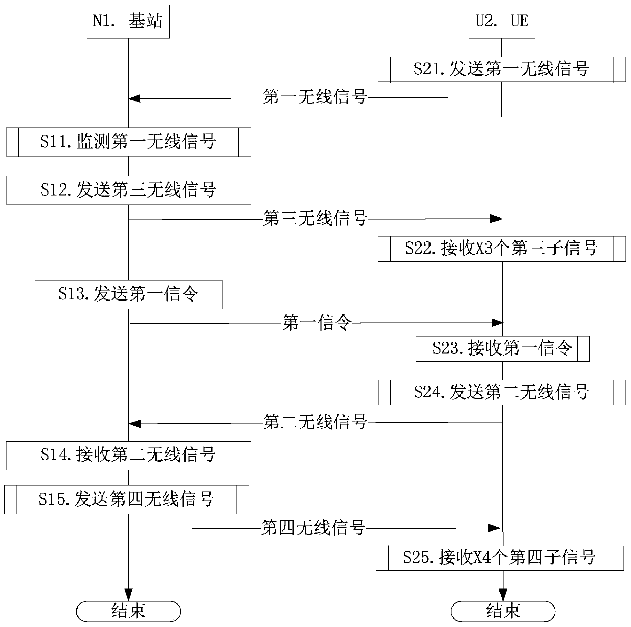
[0157] Embodiment 1 illustrates the transmission flow chart of wireless signals, as attached figure 1 shown. in the attached figure 1 In , the base station N1 is the maintenance base station of the serving cell of the UE U2.
[0158] for base station N1 , monitor the first wireless signal in step S11, send the third wireless signal in step S12, send the first signaling in step S13, receive the second wireless signal in step S14, and send the fourth wireless signal in step S15 .
[0159] for UE U2 , send the first wireless signal in step S21, receive X3 third sub-signals in step S22, receive the first signaling in step S23, send the second wireless signal in step S24, receive X4 in step S25 The fourth sub-signal.
[0160] In Embodiment 1, the first wireless signal includes X1 first sub-signals, and the second wireless signal includes X2 second sub-signals. The X1 is an integer greater than or equal to the X2, and the X2 is a positive integer. The first sub-signal is g...
Embodiment 2
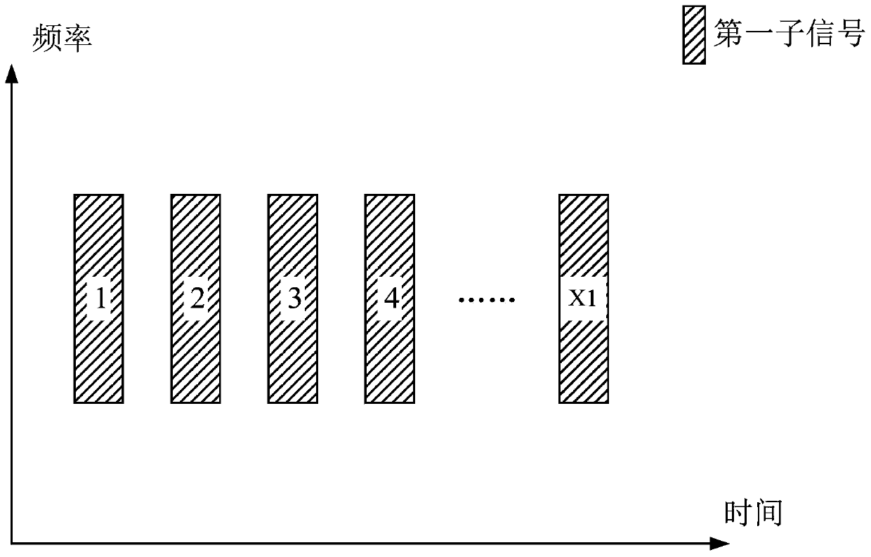
[0177] Embodiment 2 illustrates the schematic diagram of the first wireless signal, as shown in the attached image 3 shown. in the attached image 3 In , the horizontal axis represents time, the vertical axis represents frequency, and each rectangle filled with oblique lines represents the first sub-signal. In Embodiment 2, the first wireless signal includes X1 first sub-signals, where X1 is a positive integer, and the first sub-signals are generated by a characteristic sequence.
[0178] In sub-embodiment 1 of embodiment 2, the transmission channel corresponding to the first wireless signal is RACH (Random Access Channel, random access channel).
[0179] In sub-embodiment 2 of embodiment 2, the physical channel of the first wireless signal is PRACH (Physical Random Access Channel, Physical Random Access Channel).
[0180] In sub-embodiment 3 of embodiment 2, the characteristic sequence is a preamble.
[0181] In sub-embodiment 4 of embodiment 2, the characteristic sequen...
Embodiment 3
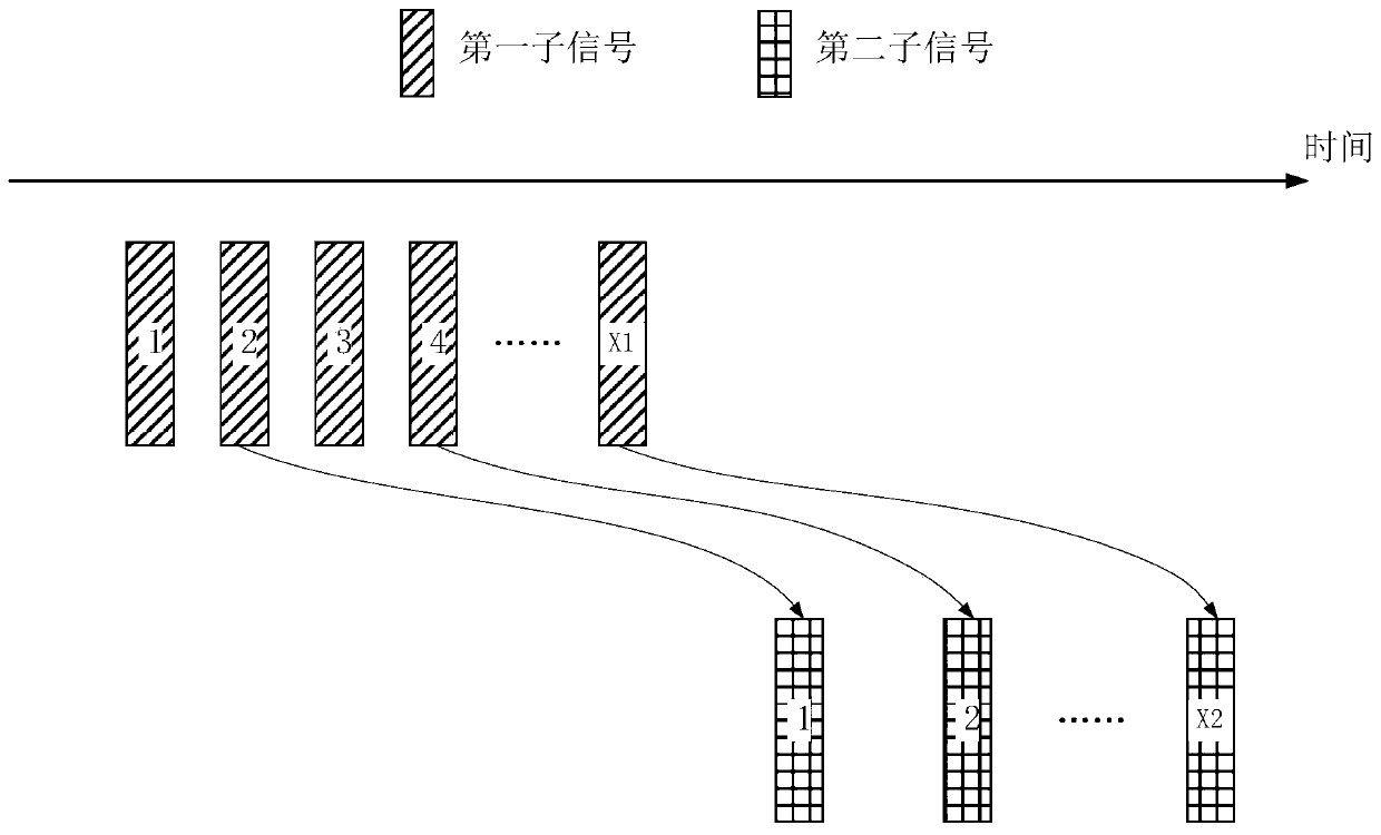
[0191] Embodiment 3 illustrates a schematic diagram of the relationship between the first wireless signal and the second wireless signal, as shown in the attached image 3 shown. in the attached image 3 , the horizontal axis represents time, each rectangle filled with diagonal lines represents the first sub-signal, each rectangle filled with cross-lines represents the second sub-signal, and the curve with arrows represents the connected first sub-signal and second sub-signal correlation between.
[0192] In Embodiment 3, the first wireless signal includes X1 first sub-signals, and the second wireless signal includes X2 second sub-signals. The X1 is an integer greater than or equal to the X2, and the X2 is a positive integer. The first signaling is used to determine X2 first sub-signals among the X1 first sub-signals, the configuration information of the X2 second sub-signals is respectively related to the X2 first sub-signals, and the The configuration information include...
PUM
 Abstract
Description
Claims
Application Information
 - R&D
- Intellectual Property
- Life Sciences
- Materials
- Tech Scout
- Unparalleled Data Quality
- Higher Quality Content
- 60% Fewer Hallucinations
Browse by: Latest US Patents, China's latest patents, Technical Efficacy Thesaurus, Application Domain, Technology Topic, Popular Technical Reports.
© 2025 PatSnap. All rights reserved.Legal|Privacy policy|Modern Slavery Act Transparency Statement|Sitemap|About US| Contact US: help@patsnap.com