
A Condensable Porous Steady Flow Device Heat Exchanger

A technology of steady flow device and shell-and-tube heat exchanger, which is applied in the direction of indirect heat exchanger, heat exchanger type, heat transfer modification, etc. Heat transfer and other issues to achieve the effect of reducing noise and vibration, inhibiting backflow, and enhancing heat transfer

Active Publication Date: 2019-03-08
济宁市邦达煤化工有限公司
View PDF6 Cites 0 Cited by
  • Summary
  • Abstract
  • Description
  • Claims
  • Application Information

AI Technical Summary

Problems solved by technology

However, it was found during the operation of this device that the space A formed between the three pipes is relatively small because the pipes are tightly combined, because the space A is formed by the convex arc of the three pipes, so most of the space A Narrowness will make it difficult for the fluid to enter and pass through, resulting in a short circuit of the fluid, which affects the heat transfer of the fluid and cannot play a good role in stabilizing the flow
Simultaneously because the many tubes of above-mentioned structure are combined together, manufacture difficulty

Method used


Image

  • A Condensable Porous Steady Flow Device Heat Exchanger
  • A Condensable Porous Steady Flow Device Heat Exchanger
  • A Condensable Porous Steady Flow Device Heat Exchanger

Examples


Embodiment Construction

[0043] The specific embodiments of the present invention will be described in detail below in conjunction with the accompanying drawings.

[0044] In this article, if there is no special explanation, when it comes to formulas, " / " means division, and "×" and "*" mean multiplication.

[0045] It should be noted that, unless otherwise specified, the two-phase flow mentioned in the present invention is a vapor-liquid two-phase flow, where the vapor phase can be condensed into a liquid phase during the heat exchange process.

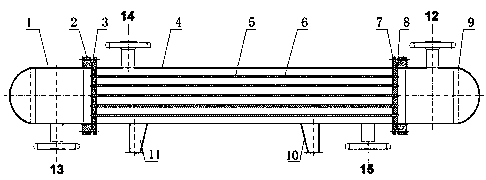
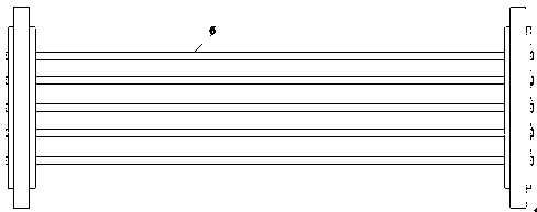
[0046] like figure 1 A shell-and-tube heat exchanger is shown, and the shell-and-tube heat exchanger includes a shell 4, a heat exchange tube 6, a tube-side inlet pipe 12, a tube-side outlet pipe 13, a shell-side inlet connecting pipe 14 and a shell The outlet connecting pipe 15; the heat exchange tube bundle composed of a plurality of parallel heat exchange tubes 6 is connected to the front tube sheet 3 and the rear tube sheet 7; the front end of the fron...


PUM


Abstract

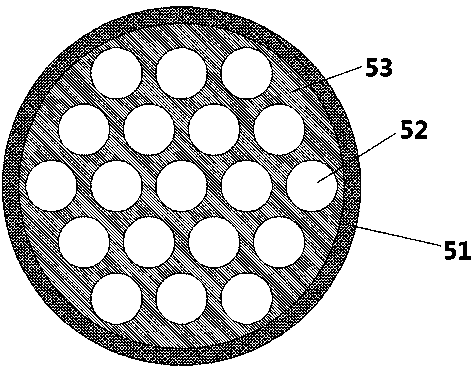
The invention provides a vapor-liquid two-phase flow tube and shell heat exchanger. The tube and shell heat exchanger comprises a shell. The two ends of the shell are provided with end sockets. Tube plates are arranged at the junctions between the end sockets and the shell. Heat exchange tubes are connected with the tube plates at the two ends. A vapor phase in vapor-liquid two-phase flow can be condensed into a liquid phase in the heat exchange process. The vapor-liquid two-phase flow flows in a tube pass. Current stabilizers are arranged in the heat exchange tubes. Each current stabilizer comprises a core body and an outer shell, the core body is arranged in the outer shell, the outer shell is connected and fixed to the inner wall of the corresponding heat exchange tube, the core body isan integrated structural part extending in the length direction of the outer shell, and the structural part is provided with a plurality of through holes. The current stabilizer heat exchanger of a novel structure, provided by the invention, conducts enhanced heat transfer when the vapor-liquid two-phase flow flows in a pipeline. Meanwhile, vibration of the pipeline is weakened, and noise is lowered.

Description

technical field [0001] The present invention relates to a shell-and-tube heat exchanger, and more particularly to a two-phase flow heat exchanger containing condensable gas. Background technique [0002] Vapor-liquid two-phase flow heat exchange widely exists in various heat exchange devices. Due to the existence of the vapor phase in the heat exchange process of vapor-liquid two-phase flow, the heat exchange efficiency will be low, the heat exchange will be deteriorated, and the fluid flow process will be unstable. , and will lead to the occurrence of water hammer phenomenon. When the gas-liquid phase of the two-phase working fluid is not uniformly mixed and flows discontinuously, the large-sized liquid mass will occupy the air mass space at high speed, resulting in unstable two-phase flow, which will violently impact equipment and pipelines, resulting in strong vibration and noise , which seriously threatens the safety of equipment operation. [0003] The inventor also d...

Claims


Application Information

Patent Timeline
Patent Type & Authority Patents(China)
IPC IPC(8): F28D7/16F28F1/00F28F13/02
CPCF28D7/16F28F1/00F28F13/02F28F2250/00
Inventor 郭春生刘勇齐超宋金圣邓伊涵高军宁淑荣张斌曲芳仪陈子昂年显勃李言伟
Owner 济宁市邦达煤化工有限公司
Learn More